Computer “Mikro-80” – a modern replica
The computer “Mikro-80” was made in the Soviet Union in 1980 by a team of enthusiasts. In 1982 the magazine “Radio” began publishing its documentation and schematics. This was the first accessible personal computer in the USSR; in that era, only single digits of people in the country could have a home computer – there were only imported units or enterprise-grade desktop computers.
A complete “Mikro-80” contained about 200 microchips. Very few people opted to replicate this complex design, so its popularity was limited.
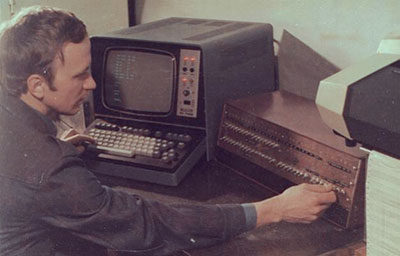
This is a photo of one of the computer’s authors, Sergey Nikolaevich Popov, with his “child” (photograph retrieved from zxbyte.ru):
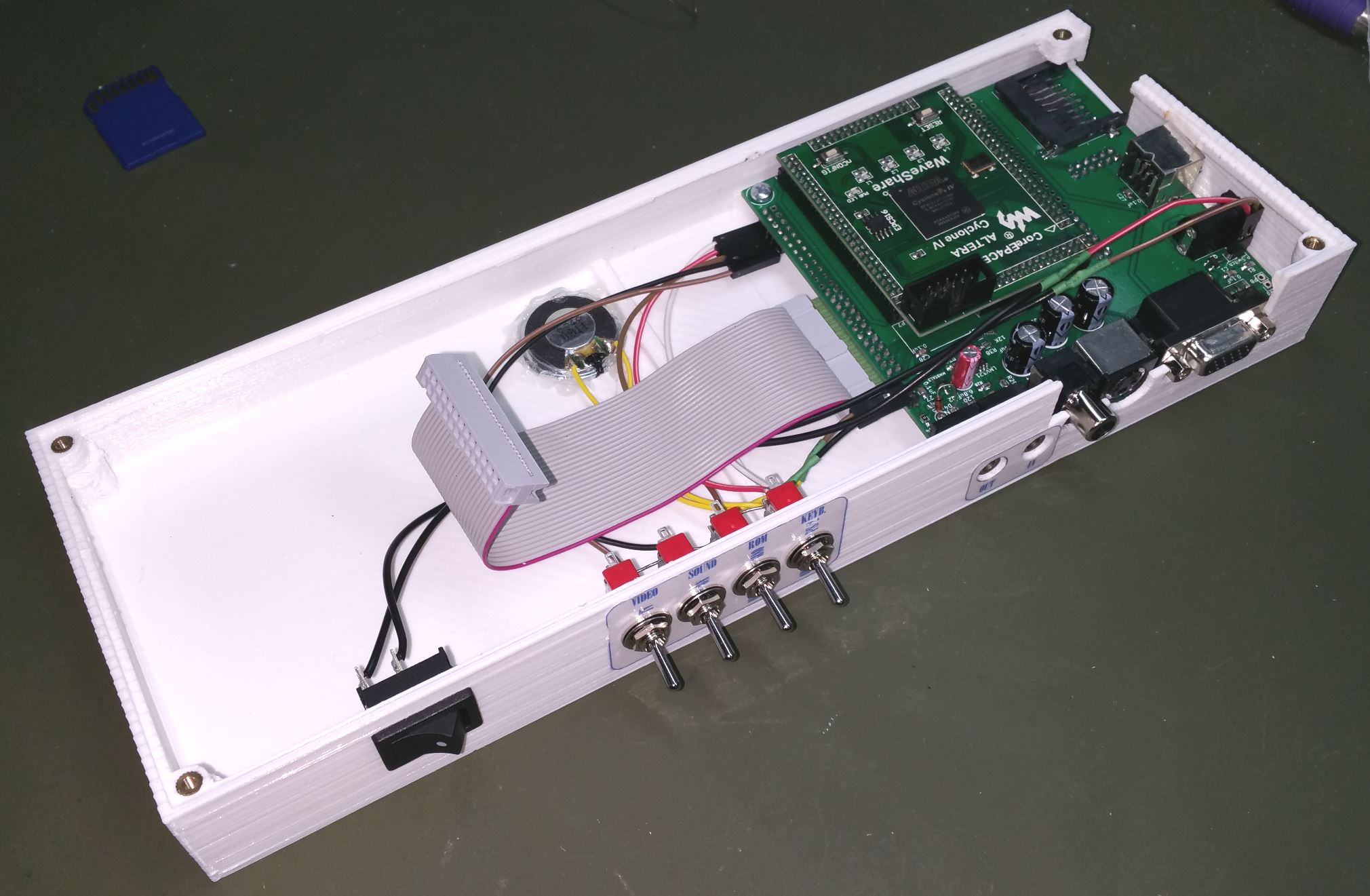
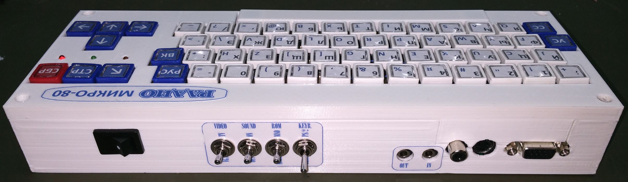
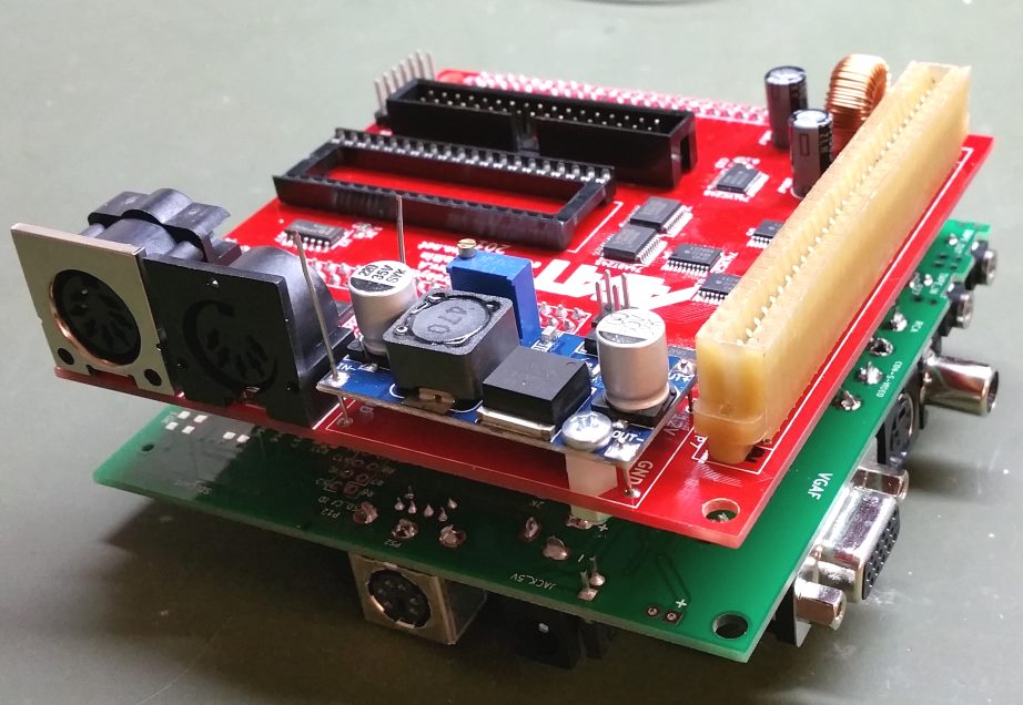
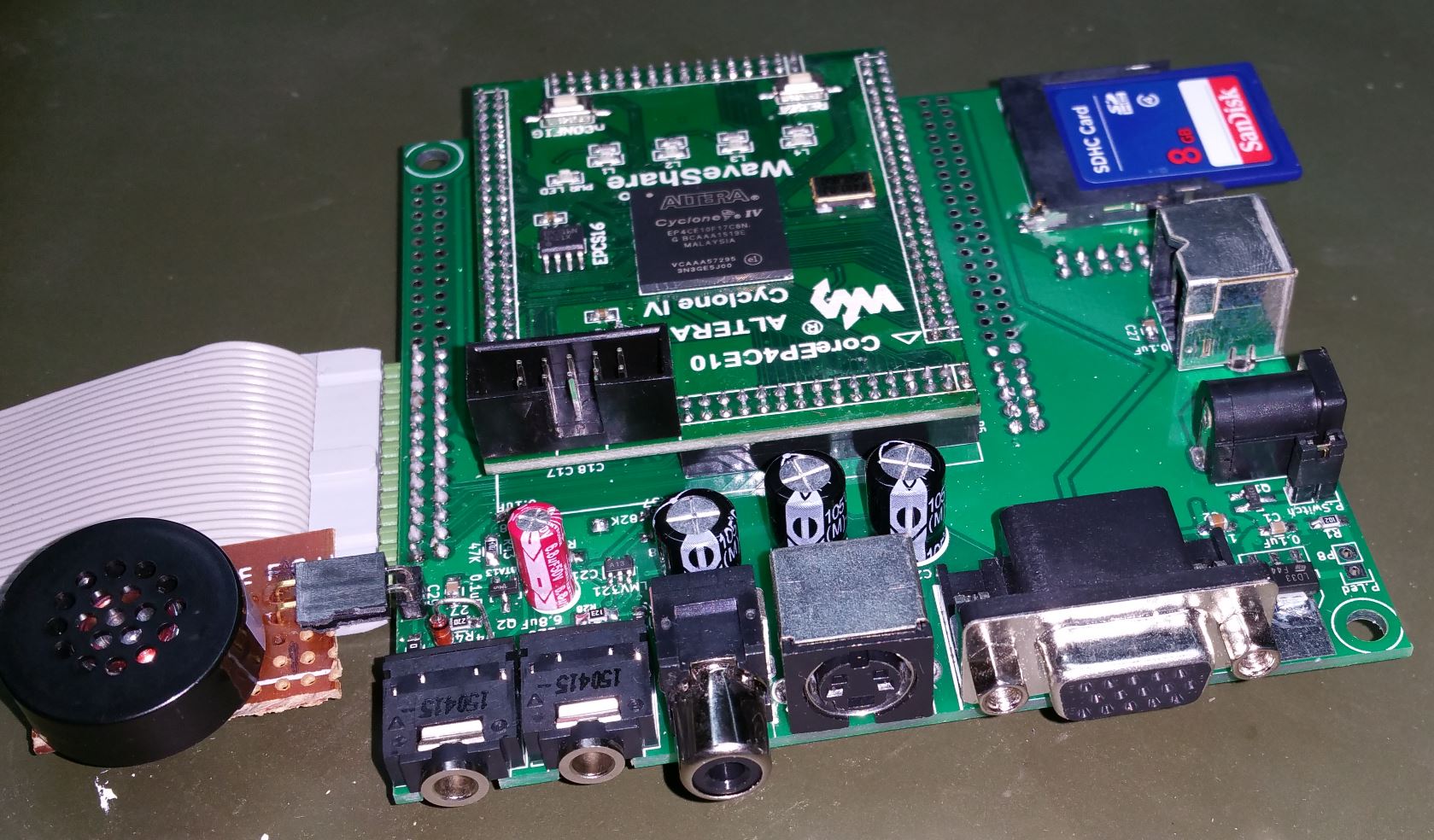
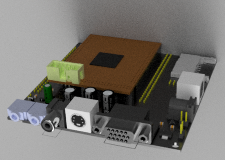
Using my newly developed platform Retrobyte, I replicated this computer using modern components. Thanks to the FPGA, I had to use only seven microchips. This is what my version of the computer looks like:
In this photograph, it can be seen that the computer takes up the smaller portion of the case – the size of the board is only 10x10cm:
The specifications of the original model are as such:
- Processor: KR580VM80A (Intel 8080 clone)
- Memory: 64 KB RAM (55KB is accessible by the user), 2 KB ROM
- Output device: home television – 64 x 32 black and white characters
- External memory device: a home tape cassette (speed of exchange – 1500 baud)
In addition to this, my version of the computer has the following:
- Two versions of ROMs – one with the classic “Mikro-80” MONITOR and the second with a MONITOR compatible with the “Radio-86RK” computer (“M/80K”). The ROM is chosen by the toggle switch before the computer’s startup.
- When the original MONITOR “Mikro-80” is chosen, BASIC is loaded onto the ROM before the computer is turned on and can be launched with the command G.
- There are RCA and S-Video outputs for video signal
- The toggle switch chooses An option to output to a VGA display (using the resolution of 1024 x 768 and refresh rate of 70Hz) instead of a TV.
- The toggle switch also selects the ability to use an external PS/2 keyboard.
- A speaker was installed, to which the cassette input and output signal are duplicated (this can be turned off).
- The SD card’s controller was initially designed vinxru with the “Mikro-80” adaptation by vlad6502 (massive thanks to those two for their work!).
The SD card only works with the “M/80K” MONITOR since the ability to use the external ROM implemented by the controller is added to it.
To access the contents of the SD card, I used a shell written by vinxru and adapted to the “Micro-80” by vlad6502 is also used. I only had to change the screen size from 25 lines to 32.
The loader must be run with the commands R0, FF and G to launch the shell. I changed the port addresses in the loader since vlad6502 uses the inverted bits A0 and A1 of the address bus in his “Micro-80” version compared to the standard variant. Also, I fixed a mistake in the design of the controller, which consisted of the inability to change the directions of the output of the external port.
The controller is a small board with an Atmega8L microcontroller connected to the Retrobyte board’s SD card and the FPGA outputs. This microcontroller functions at 3.3V voltage and can be directly connected to the FPGA and SD card. I made a small mistake with the controller board sizes and used wires to connect it.
My China-made USBASP programmer refused to upload the firmware onto the microcontroller Atmega8L, so the Arduino Nano was used instead.
The processor КР580ВМ80А (Intel 8080’s clone) is also threaded into the FPGA. Vslav performed a reverse-engineer of the processor and made its exact FPGA copy: https://habrahabr.ru/post/249613/, which I used in this project.
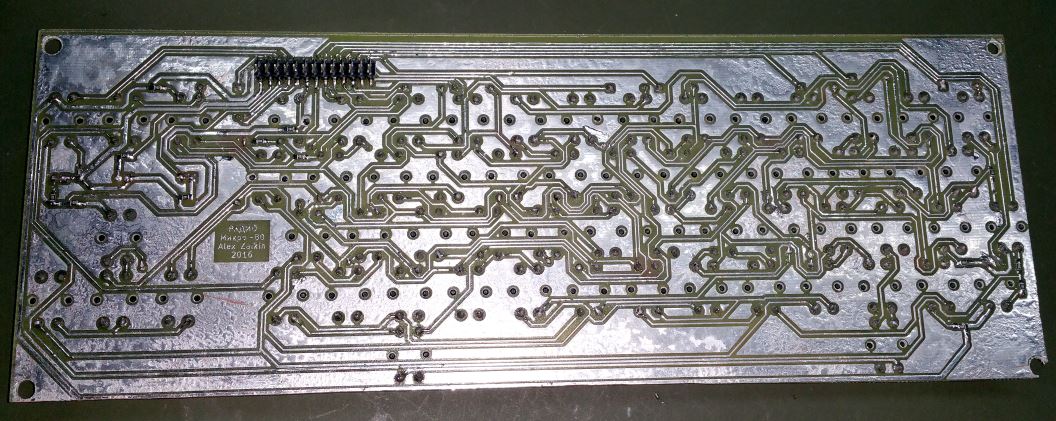
The keyboard had ordinary tactile buttons (12 x 12 mm) soldered onto the PCB. Ordering a board of that size would be too expensive, so I made it myself. Attempts to transfer the image onto a PCB of that size using a laser printer were unsuccessful – the transfer onto the board was inconsistent throughout its whole area. In some places, the toner peeled away or shifted slightly.
This was an excellent reason to try the new ‘photo-etching’ technology. I bought a one-sided board with the photoresist film already on it and a solution to develop it. I lit the board with an ordinary luminescent lamp. The time that the board was exposed to light was deduced using a small piece; that piece was exposed to sunlight as time passed. After the small cut-off was fully developed, the time for the main PCB was chosen, judging from the best-quality marks on the test piece.
I liked the result; this is my preferred method for future projects.
After the board was etched, I tinned it, applying a mixture of old soldering paste and liquid flux before heating it with a thermal fan. Next, I drilled over 350 holes in the board for the buttons.
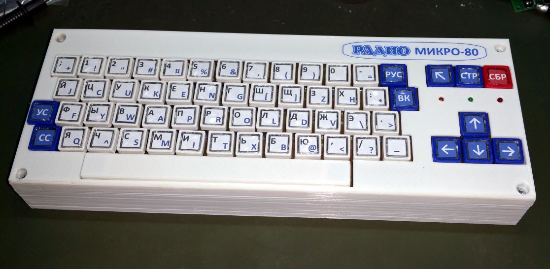
I also ordered some transparent caps for the buttons, so it would be possible to add labels. When they arrived, they turned out to be too small; I had to 3D print frames for the caps to increase their area for the fingers—the “Spacebar” button I also printed out and mounted onto two buttons.
As a result, the keyboard was very compact:

I kept the layout and positioning of the keys from the magazine version of this computer, except I also added a “RESET” button; additionally, instead of the toggle “RUS” button, I installed a usual switch. To indicate the current status (RUS/LAT), I added an indicator LED on the keyboard (yellow) and another one to indicate SD card access (green).
Even though the finished keyboard functioned well, the tactile buttons were not the best choice – they have a slight pressing motion and shift under the fingers when pressed. I will probably try out another solution for the next project.

I created the enclosure for the computer in Autodesk Fusion 360. This program was my first try; it’s free for hobby use, and I immensely enjoyed it. I exported the PCBs of Retrobyte and the keyboard from KiCAD (where I worked on them) into FreeCAD and, from there, into Fusion 360. All that was left was to create the body around those boards. The keyboard housing just barely fit into the working space of my 3D printer. I printed it in PLA since I couldn’t be sure that the ABS wouldn’t warp at the edges of the printer’s working space. Additionally, the PLA is sturdier and less prone to deformation, essential for relatively thin-walled cases like this one.
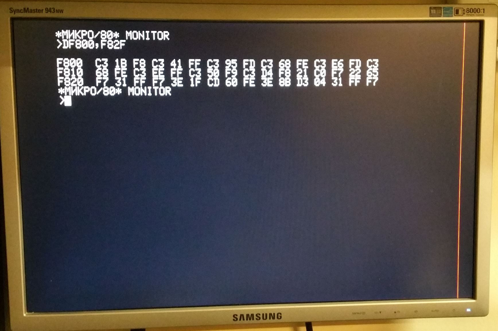
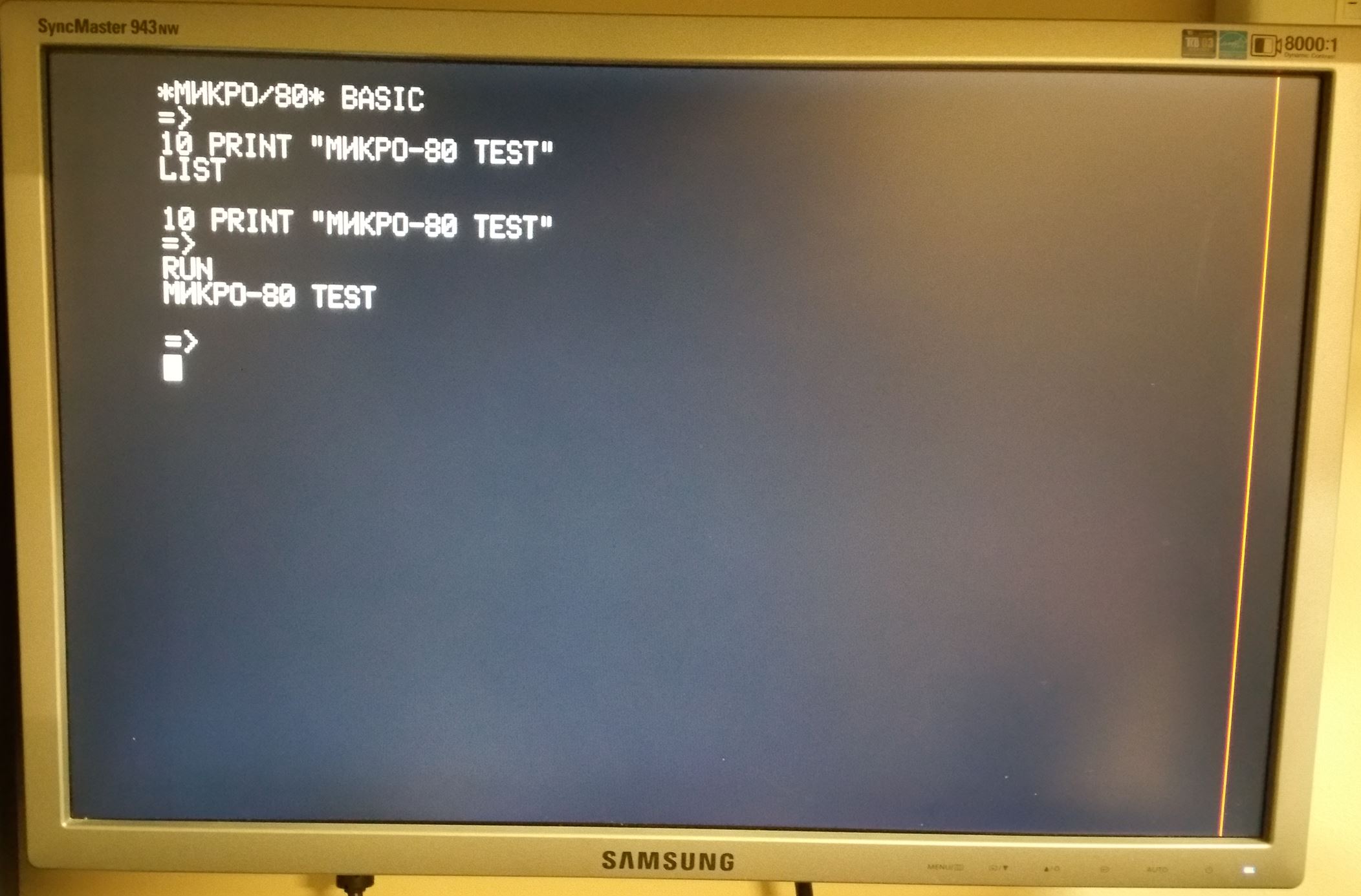
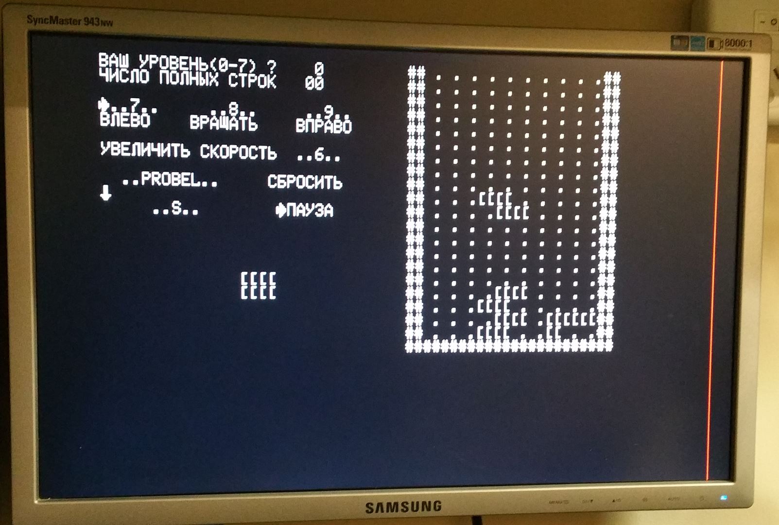
Not very many programs exist for the “Mikro-80”. Some programs from the “Radio-86RK” computer can also be launched on the “Mikro-80”, but even then, most of them require some degree of modification (mainly due to the way “Mikro-80” shows the cursor or its processing of the key presses). I adapted some and planned to make a separate post about them. For now, here are some photographs of the working computer’s screen:

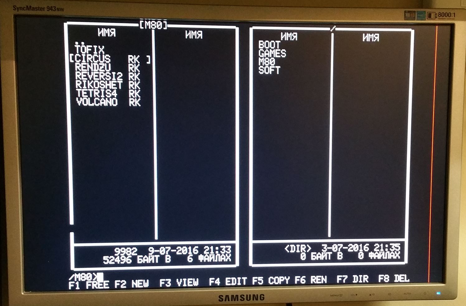

Here is the content of the SD card, which has all the necessary files to run the SD shell and programs that can be run on the “Mikro-80” computer: sd_mikro80.
Catch you later!
2 thoughts on “Computer “Mikro-80” – a modern replica”