Logic probe with sound indication
I need a logic probe to troubleshoot some of my designs. I didn’t want to reinvent the wheel, so I checked the existing designs. I found that the design from talkingelectronics.com is most suitable for my needs. The main benefits of this design are a sound indication and 3rd LED (for pulses). It is possible to buy a kit there, but I decided to design my own PCB because the one in the kit is not convenient to use from my point of view.
By the way, I’ve found this site quite interesting. There are heaps of small but exciting designs with explanations and schematics. Many of them can be ordered as a kit.
I’ve put the device into a small box with a binding post to connect different probes. Also, it allows you to locate the device conveniently while testing a design with the compact probe.
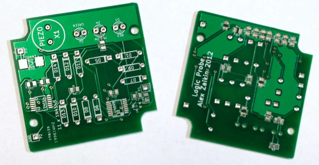
I’ve used SMD components, so I created a PCB that fits the “Hammond-1551RBK” enclosure (50mm х 50mm х 20mm). I designed the PCB in KiCAD. It can be downloaded here.
This is the PCB:
I used 2-layers and put some resistors and capacitors on the bottom side of the board. Generally, it is not the best practice, but I wanted to utilise my 1N4148 diodes, one hundred of which I had bought for a couple of dollars some time ago, so I ran out of space on top of the board quite quickly.
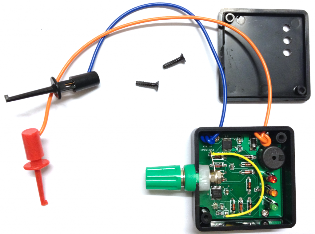
Here is the board in the enclosure:
The device started to work immediately and required only a minor adjustment of the “0” threshold by a trim pot. I used LED standoffs to make LEDs align properly with holes drilled in the cover. A label was glued on top of the box.
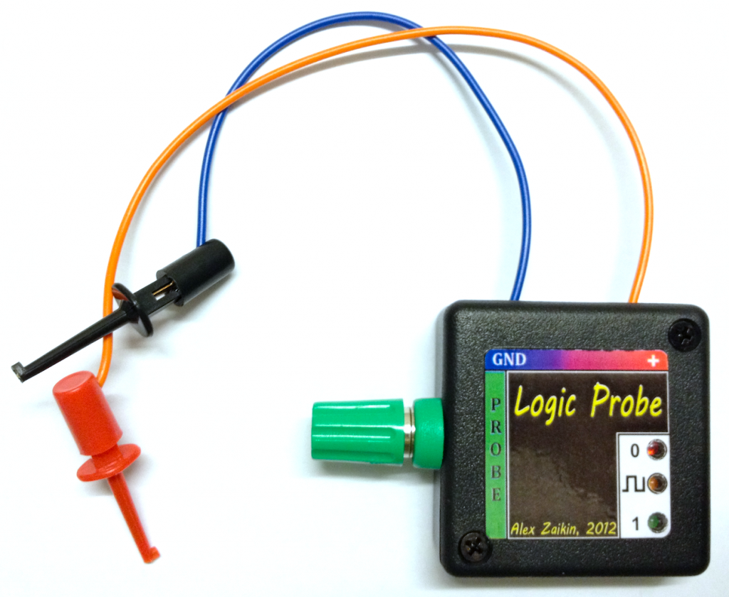
I used the free Inkscape program to design the label. I had to print several trials until I was happy with its design and alignment against LEDs. I printed it out on regular paper with the best quality, cut the holes for LEDs and painted its edges with a black gel pen. Then I laminated the label with a thin 80-micron film. After carefully cutting the label from the paper, I painted the edge with a gel pen to hide the white paper.
I used spray glue to fix the label in its place. I’ve protected the LED holes from spray with a piece of sticky tape which I removed before placing the label on the box. The excessive glue was removed with turpentine. Here is the result:
I’ve found out that it is very convenient to use the probe. I can choose a suitable probe for a task and connect it to the binding post on the device. Also, it is very convenient to have a sound indication, so you don’t need to switch your attention from the testing design, reducing the probability of accidentally shorting something with a probe. This device cannot replace an oscilloscope or a logic analyser, but it can help a lot when such power is excessive.
See you!
