Review of LCR-F meter from Dr. Le Hung
Some time ago I got an old computer for free. Nothing happened when I tried to turn it on, so I assumed that the power supply was broken. It is a small IBM computer in a horizontal desktop case. It has a power supply integrated into the motherboard. Some capacitors look damaged, so it can be a simple solution. I still don’t have an ESR meter, so it is an excellent reason to build one.
I’ve checked several designs and decided to build the one from Dr Le Hung. It is pretty accurate, easy to calibrate and has a lot of additional functions.
The main drawback of its solution is the lack of source code for the microcontroller. It means adding more functions, changing something, or using a different MCU is impossible. From another point of view, Le Hung sells DIY kits with a preprogrammed ATMega microcontroller and checks high tolerance components, which helps to avoid a complicated calibration process, so I’ve decided to order the kit. It took about two weeks to arrive.
There are no SMD components in the kit, and it is straightforward to build even for beginners:

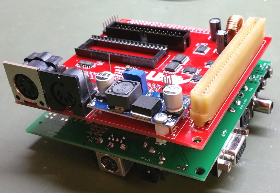
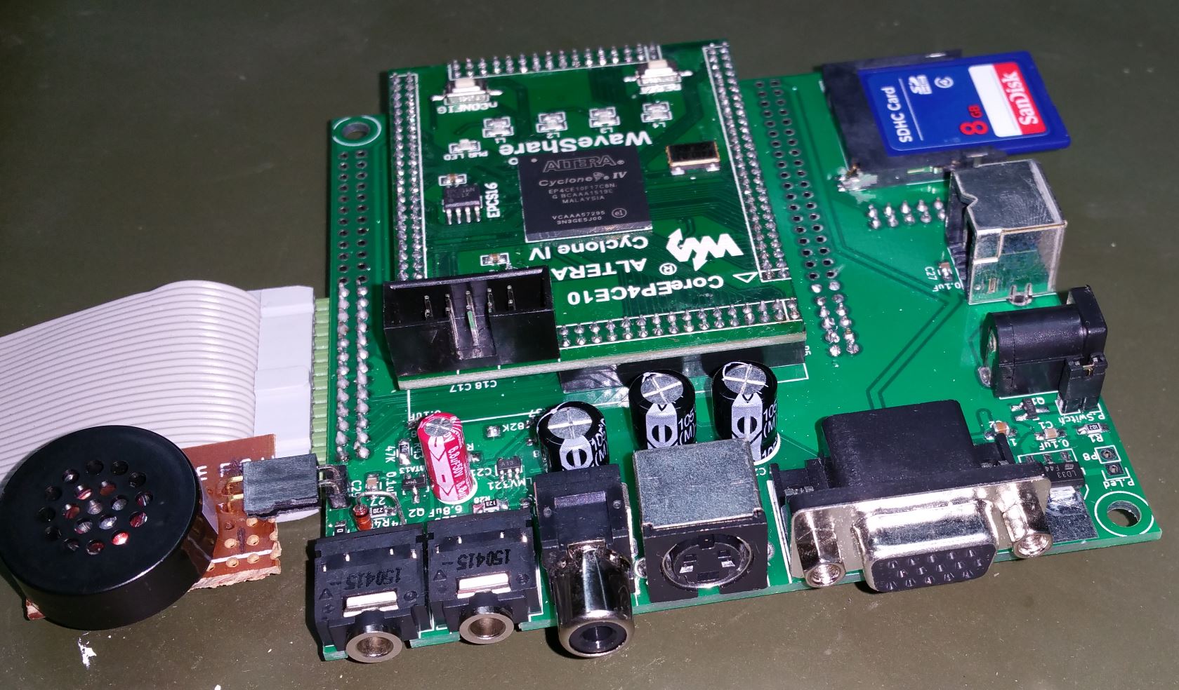
The PCB has quite good quality with a solder mask, but, unfortunately, it is a single-layer:

It affected the PCB size as well as the need for jumpers. I’ve counted 15 of them, so ensure you have a proper wire for this. Also, there is no silkscreen on the PCB at all. I had to use a PCB draw to ensure appropriate components were used, which increased the chances of a mistake.
I couldn’t find a case for the perfectly fitting device, so I assume that the PCB hasn’t been designed for a particular case. A display, battery and switch made finding a suitable case tricky. Finally, I’ve decided to use the “Serpac-273” case. It is a bit large for the PCB, but it has a 9V battery compartment, and its high is perfect to fit the display and the switch actuator. The PCB holes in the case don’t match, so I had to drill holes in the bottom and cover them with rubber stands:

Several Russian-made capacitors in the kit have good stability and tolerance. Le Hung assured me that he checks them all, so there shouldn’t be any problems.
All ICs are mounted in sockets which is essential for beginners.
Unfortunately, the aluminium caps in the kit are G-LUXON branded. It is probably all right for the big bipolar cap because it doesn’t have a lot of stress in this schematic, so I’ve decided to keep it. But I believe it is not the best choice for the two power supply decoupling caps. Despite their working condition, it is only a matter of time. I’d recommend replacing them with good-brand capacitors. I put it into the drawer with other useless stuff in case I need them to repair something urgently.
For 5V conversion, the good old 7805 is used. It is all right to use the device with an external power supply. But it is not the best solution if a 9V battery is used. 7805 has a 2V voltage drop, so the device will stop working when the voltage reaches 7V, but a battery still has 25-30% of its charge. 9V batteries are expensive, so throwing them away with a quarter of their capacity still left is not wise. To avoid this, a modern one has to be used. I chose LF50A, which has a voltage drop down to 0.2V. It means the device will work until the battery voltage reaches 5.2V, which happens when the battery is almost completely flat. LF50A has a 1% output voltage tolerance which is important for a measurement device. Its retail price is less than $1, and this money will be saved on the first battery. Its pinout in the TO-220 case is the same as 7805, so no PCB modifications are required. But input and output decoupling capacitors C1 and C11 must be replaced with ceramic 0.1uF and aluminium 2.2uF, respectively. It shouldn’t be a problem because C1 and C11 are those G-LUXON capacitors that went to the rubbish bin anyway. Le Hung suggests using 8.4В rechargeable batteries instead of 9V batteries. Still, even in this case I believe that the voltage regulator replacement is beneficial because it will increase the time between recharges and improve a battery’s lifespan.
It was a piece of cake to solder it all together, thanks to the solder mask and big pads. It was ready and running by the end of the night. It didn’t require any adjustments apart from the display contrast with a trim pot.
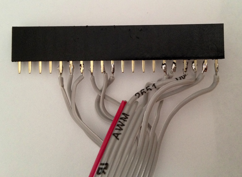
Honestly, I wouldn’t say I like how the LCD is connected. I had to solder a ribbon cable to header pins – not my favourite stuff. Furthermore, the order is inconsistent, creating even more problems and points to make a mistake. Here is how it looks:
It also took a while to mount the case. I’ve soldered the wires to the PCB as Le Hung recommended to improve accuracy.
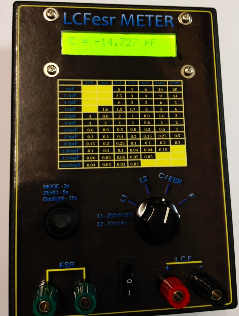
The test proved the high accuracy of the device.
Le Hung is excellent in communication which is a great benefit of the kit.
I enjoyed building this device and am very happy to have this device on my bench top:
It is a perfect weekend project for hobbyists with different skills. Its drawbacks are easy to fix and don’t affect the device’s functionality. If you want to build an ESR meter for yourself, I’d recommend taking a closer look at this kit. See you!