HD44780-compartible LCD display and STM32.
HD44780-compatible LCD digital-alphabetical displays are very convenient to use in hobby projects. They exist in different sizes and are quite cheap. The most popular are 2 line modules with 16 characters per line (16×2). Also, 8х2, 16х1, 20х2, 20х4 and 40х2 modules exist.

For my “AGAT-7” retro computer project, I use a 20×4 LCD module. Most modules are designed to use a 5V power supply, but 3.3V modules also exist. They are not as popular as 5V modules and are usually twice as expensive, so I prefer to use 5V modules with transition IC if a 3.3V microcontroller is used (i.e. STM32). This IC costs less than $1 and is cheaper than 3.3V modules. LCD control RS, R/W and E pins are used. Data is transported by an 8-bit bus, but switching to the 4-bit bus is possible. In this case, each byte is sent in two steps. It means we need 7 to 11 pins to control the module. The 8-bit data bus is easier to use, has higher speed and requires less microcontroller time than the 4-bit bus.
There are also two methods of controlling the intervals between commands – timer and reading the “ready” bit. In the second method, the module uses the highest bit of the data bus as the “ready” bit. Although the first method is less time effective, it is sometimes preferable. For instance, when a 3.3V microcontroller is used, the first method allows avoiding expensive two-way “5V <-> 3.3V” level transition IC. Also, we can spare one pin with this method because R/W signal control is not required. Usually, I prefer to use the timer method with an 8-bit data bus in my projects, which requires ten microcontroller pins and a cheap voltage transition chip.
Modules can be supplied with different charsets, so if you use languages other than English in your project, it is better to ensure you buy the proper module. Also, several user characters can be programmed in the module.
Pinouts can be different in different modules, but the most common is the following:
-
- GND
- Vcc (+5V)
- Contrast setup (Vo)
- RS
- R/W
- Enable (E)
- Bit 0 (Low bit for 8-bit interface)
- Bit 1
- Bit 2
- Bit 3
- Bit 4 (low bit for 4-bit interface)
- Bit 5
- Bit 6
- Bit 7 (the high bit)
- Background light power supply for modules with it (anode)
- Background light power supply for modules with it (cathode)
The background light is recommended to connect through a 50-100 Ohm current limiting resistor. The contrast can be set up with a 10-20k trim pot bound as a voltage divider (A and B to 5V, W – to pin Vo).
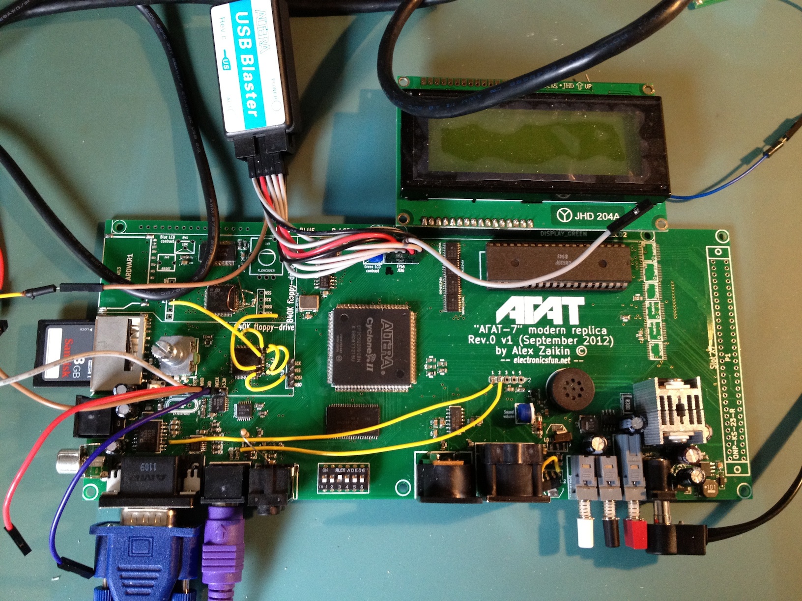
Here is an example of HD44780 LCD module usage from one of my projects (“AGAT-7”). It is connected to an STM32L152R6 microcontroller used as a 140K floppy-drive emulator. The schematic is:

Let’s initialise the microcontroller with its usual commands. Also, let’s set up delay functions in ms and us. I used a TIM6 timer for delays, but a simple loop with measured time will also do the job.
#include "stm32l1xx.h"
#include "stm32l1xx_conf.h"
#include "stm32l1xx_gpio.h"
#include "stm32l1xx_exti.h"
#include "stm32l1xx_syscfg.h"
#include "misc.h"

void delay_us(uint16_t usv)                 // Delay in us
{
  TIM6->PSC=32-1;
  TIM6->ARR=usv;
  TIM6->DIER = TIM_DIER_UIE;
  TIM6->SR &= ~TIM_SR_UIF;
  TIM6->CR1 &= ~TIM_CR1_ARPE;
  TIM6->SR = 0x00;
  TIM6->CR1 |= TIM_CR1_CEN;

  while (TIM6->SR == 0)
  {}
}

void delay_ms(uint16_t msv)            // Delay in ms
{
 uint16_t i;
 for(i=0; i<msv; i++)="" delay_us(1000);="" }="" void="" stm_init()="" a="" microcontroller="" initialisation="" {=""  ="" int="" i;="" system="" clock="" rcc-="">CR|=RCC_CR_HSION;
  while (!(RCC->CR & RCC_CR_HSIRDY));             // Wait until it's stable
  RCC->CFGR|=RCC_CFGR_PLLDIV_0 | RCC_CFGR_PLLMUL_0;   // Switch to HSI as SYSCLK
  RCC->CR|=RCC_CR_PLLON;                              // Turn PLL on
  while (!(RCC->CR & RCC_CR_PLLRDY));             // Wait PLL to stabilise

  //Setting up flash for high speed
  FLASH->ACR=FLASH_ACR_ACC64;
  FLASH->ACR|=FLASH_ACR_LATENCY;
  FLASH->ACR|=FLASH_ACR_PRFTEN;

  RCC->CFGR|=RCC_CFGR_SW_1 | RCC_CFGR_SW_0;           // Set PLL as SYSCLK
  RCC->CR&=~RCC_CR_MSION;                         // Turn off MSI

  //Enabling clock for GPIOB & GPIOC
  RCC->AHBENR|=RCC_AHBENR_GPIOCEN;
  GPIOC->MODER = (uint32_t) 0x5555000;
  GPIOC->OTYPER &= (uint16_t) 0xFF;
  GPIOC->OSPEEDR = (uint16_t) 0xAAAA000;
  GPIOC->ODR = (uint32_t) 0;

  RCC->AHBENR|=RCC_AHBENR_GPIOBEN;
  GPIOB->MODER = (uint32_t) 0x155000;
  GPIOB->OTYPER&=~(GPIO_OTYPER_OT_8 | GPIO_OTYPER_OT_9 | GPIO_OTYPER_OT_10 | GPIO_OTYPER_OT_6 | GPIO_OTYPER_OT_7);
  GPIOB->OSPEEDR|=(GPIO_OSPEEDER_OSPEEDR8_1 | GPIO_OSPEEDER_OSPEEDR9_1 | GPIO_OSPEEDER_OSPEEDR10_1);
  GPIOB->ODR = (uint16_t) 0;

  RCC->APB1ENR |= RCC_APB1ENR_TIM6EN;                 // TIM6 timer clock
  RCC_APB2PeriphClockCmd(RCC_APB2Periph_SYSCFG, ENABLE);
}
We need to “blink” with the E signal often in communication with the module, so having a separate function, “lcd_nybble“, for this task is worth it. In your project, the timing intervals may require an adjustment because of different modules.
void lcd_nybble()
{
 char i;
 GPIOB->BSRRL=GPIO_BSRR_BS_10;
 for(i=0; i<5; i++);
 GPIOB->BSRRH=GPIO_BSRR_BS_10;         	//Clock enable: falling edge
}
To send a command to the module, it has to be set on the data bus and pins RS and R/W set to zero. After that, we need to “blink” with the E signal. Each command requires some time to finalise, in which the module is not accessible. So, time delays need to be used. As mentioned, a “ready” signal can be used instead. The delays need to be adjusted when different modules are used. Some commands require more time than others. My command function “lcd_command” is:
void lcd_command(uint16_t lcmnd)
{
  uint16_t temp_port;

  delay_us(40);
  temp_port = GPIOC->ODR & ((uint16_t) 0xC03F);
  GPIOC->ODR = temp_port | (lcmnd << 6);   //put data on output Port
  GPIOB->BSRRH=GPIO_BSRR_BS_8;             //RS=LOW : send data
  GPIOB->BSRRH=GPIO_BSRR_BS_9;             //R/W=LOW : Write
  lcd_nybble();
  if (lcmnd < 4) delay_us(1700);           // It takes longer to complete some commands
}
LCD module needs to be initialised. I use the following function for this purpose. I hope that it explains itself:
void lcd_init();
{
  GPIOC->BSRRH = (uint16_t) 0x3FC0;                    // Reset all ports
  GPIOB->BSRRH = (uint16_t) 0x7C0;                     // Reset all ports
  delay_us(40000);                                     // Wait >15 msec after power is applied
  GPIOC->BSRRL = GPIO_BSRR_BS_10 | GPIO_BSRR_BS_11;    // put 0x30 on the output port
  delay_us(5000);                                      // must wait 5ms, busy flag not available
  lcd_nybble();                                        // command 0x30 = Wake up
  delay_us(160);                                       // must wait 160us, busy flag not available
  lcd_nybble();                                        // command 0x30 = Wake up #2
  delay_us(160);                                       // must wait 160us, busy flag not available
  lcd_nybble();                                        // command 0x30 = Wake up #3
  delay_us(160);
  GPIOC->BSRRL = (uint16_t) 0xE00;
  lcd_nybble();
  delay_us(160);
  lcd_command((uint16_t) 0x10);
  lcd_command((uint16_t) 0x0C);
  lcd_command((uint16_t) 0x06);
}
After this, the module is ready to work. You can change the module behaviour with the last lines of the function. For instance, a cursor can be made visible. Please read the datasheet for details.
Also, we need functions for string and character output. My versions of the commands “lcd_write” and “lcd_char” are:
/**********************************************************/
void lcd_write(char ldata[])
{
  uint16_t temp_port;
  char k=0;

  GPIOB->BSRRL=GPIO_BSRR_BS_8;                 //RS=HIGH : send data
  GPIOB->BSRRH=GPIO_BSRR_BS_9;                 //R/W=LOW : Write

  while(ldata[k] != 0)
  {
    delay_us(40);
    temp_port = GPIOC->ODR & ((uint16_t) 0xC03F);
    GPIOC->ODR = temp_port | (ldata[k] << 6);  //put data on output Port
    lcd_nybble();
    k++;
  }
}

/**********************************************************/
void lcd_char(char ldata)
{
  uint16_t temp_port;

  GPIOB->BSRRL=GPIO_BSRR_BS_8;                //RS=HIGH : send data
  GPIOB->BSRRH=GPIO_BSRR_BS_9;                //R/W=LOW : Write
  delay_us(40);
  temp_port = GPIOC->ODR & ((uint16_t) 0xC03F);
  GPIOC->ODR = temp_port | (ldata << 6);      //put data on output Port
  lcd_nybble();
}
Finally, we need a command to locate a cursor to any position on the screen. Please remember that addresses are not linear – the third row goes after the first, and the second follows the third. It has had to be counted in the function “lcd_goto“:
void lcd_goto(uint8_t x, uint8_t y)
{
  uint8_t addr;

  switch (y)
  {
  case 0:
    addr = 0x80;
    break;
  case 1:
    addr = 0xC0;
    break;
  case 2:
    addr = 0x94;
    break;
  default:
    addr = 0xD4;
    break;
  }
  addr = addr + x;
  lcd_command((uint16_t) addr);
}
I hope that the function is quite clear.
Now we have all the necessary tools to try the LCD module. Let’s write a simple program that programs a user character and displays some strings on the screen:
int main(void)
{
  stm_init();
  lcd_init();                                // LCD initialisation
  lcd_command((uint16_t) 0x01);              // Clear screen
  delay_us(1700);
  lcd_command(0x40);                         // Start recording a cyrillyc symbol "Г" to the memory to zero place
  lcd_char(0x1f); lcd_char(0x10); lcd_char(0x10); lcd_char(0x10);
  lcd_char(0x10); lcd_char(0x10); lcd_char(0x10); lcd_char(0x00);   // The character recorded
  lcd_command(0x01);                         // Clear screen
  lcd_goto(0,0); lcd_write("********************");
  lcd_goto(0,1); lcd_write("*      A"); lcd_char(0x00); lcd_write("AT-7      *");
  lcd_goto(0,2); lcd_write("*electronicsfun.net*");
  lcd_goto(0,3); lcd_write("********************");
  while (1)
  {}
}
The program initialises the module, creates a new symbol “Г” with 0x00 code and shows an intro from my “AGAT-7′ project. Please pay attention that we need to use the “lcd_char” function instead of “lcd_write” to display a character with 0x00 code. Here is the outcome:

More helpful information can be found in a datasheet to a module.
I hope this post will help you use these modules in your projects. See you!