Clock generation in FPGA with phase accumulator. Calculation and limits.
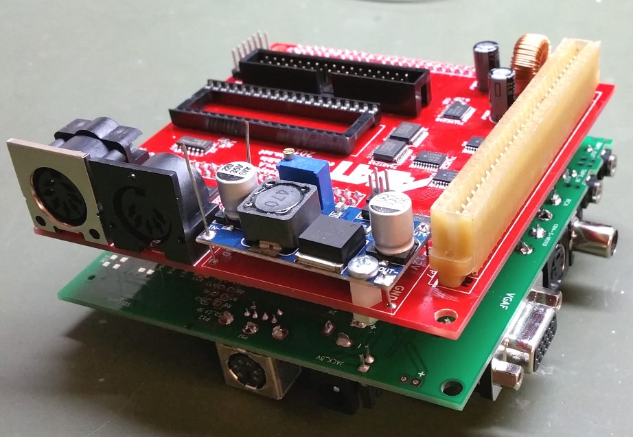
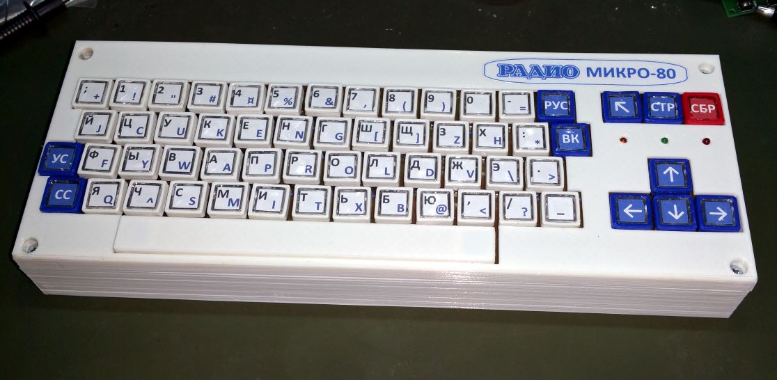
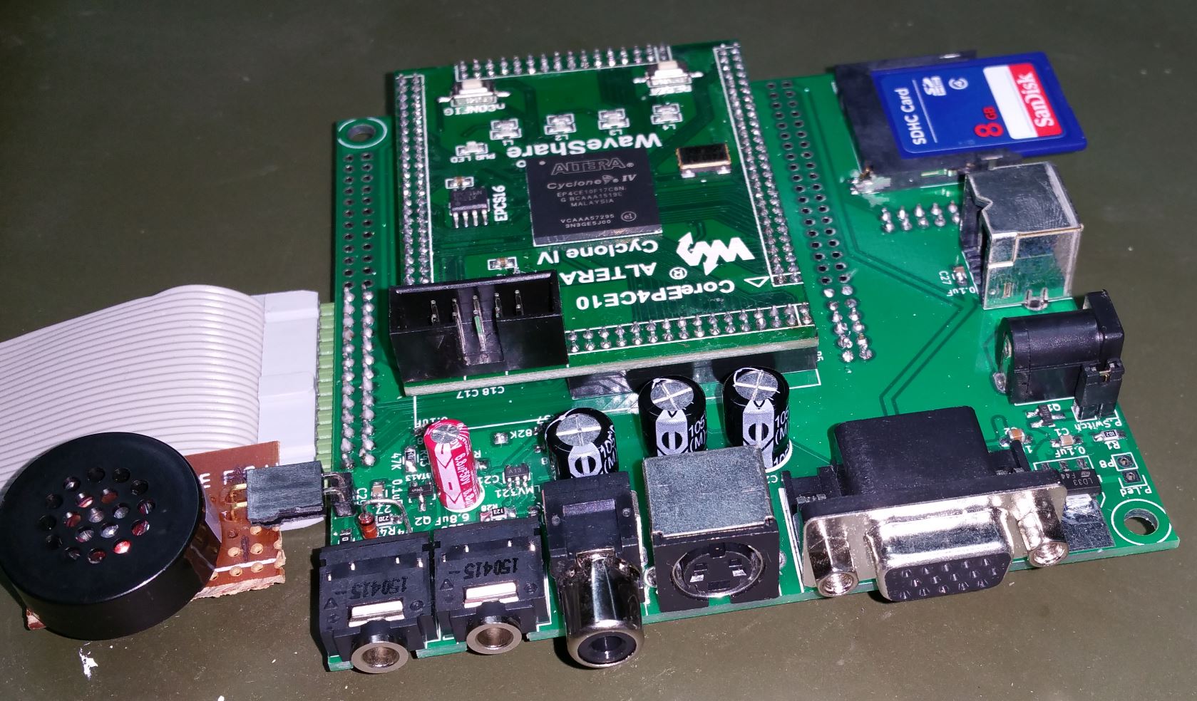
In my project of a modern replica of a retro computer, “Agat-7”, I needed to generate several clocks. The PLL built-in FPGA can produce some of them; others are a simple division of the main clock. But another group of clock signals is not as simple to get. I use a 50MHz oscillator with FPGA and produce the main system clock of 32.5MHz by PLL. It is perfect for a VGA output in 1024×768 mode and the CPU clock (32.5 / 32 = 1.016MHz), but it is not good for the TV output, which requires 10.5MHz for pixel clock and 17.734475MHz for the colour encoding subcarrier. Instead of using additional oscillators, user svofski from zx.pk.ru forum suggested I to use phase accumulator to generate such frequencies in FPGA. It is a simple but efficient method that can also generate different waveforms apart from a simple clock signal. You can have more information about it in Wikipedia.
I’ve created a simple calculator to determine the constants and accuracy of the generator:
Here is an example of a VHDL code. It generates 17.5MHz output clock from 250MHz clock using a 32-bit accumulator register:
signal acc: std_logic_vector (31 downto 0); -- It is 32-bit phase accumulator. Change if different
signal clk_main: std_logic; -- 250MHz main clock source
signal clk_gen: std_logic; -- 17.5MHz generated clock signal

process(clk_main) -- phase accumulator clock generator (adder)
begin
   if (clk_main'event and clk_main = '1') then
      acc <= acc + 981707; -- use the calculated number to add it at each step
   end if;
end process;

clk_gen <= acc(31); -- use the highest bit of the accumulator for the output clock (31 for 32-bit acc.)
The idea of this method is to have an accumulator register (usually at least 32-bit) to which a certain constant is added at each step of the main clock. It causes overflow after certain periods, and the remainder goes to the next cycle, causing another overflow after some cycles. The generated clock is the highest bit of the accumulator. It will take one step less to overflow the accumulator on a certain step so that the output clock time will be less on this step. The proportion between “long” and “short” timings determines the average output frequency. Higher input frequency will make the difference between “long” and “short” steps less, making the output signal more accurate. Therefore, the disadvantage of this method is an irregular duty cycle, especially when the main and the generated frequencies are too close. Here is an example of generating 15MHz clock with a 50MHz main clock:

As you can see, despite an accurate average clock frequency, individual periods are different. If we use a 250MHz main clock, the picture becomes much better:

There are still some irregularities in the duty cycle, but they are good enough for most purposes. At least in my project, the abovementioned TV signals are generated from a 275MHz clock (produced by a PLL multiplication) with this method, and the output is quite impressive.
To use the calculator, you need to enter the main clock, the desired clock frequencies, and the intended length of the accumulator register. The best achievable frequency and its variance against the goal are calculated. If the result is not good enough, try to increase the accumulator length.
The calculator also shows how the duty cycle fluctuates from period to period compared to the ideal 50% duty cycle. To improve this parameter, the initial clock frequency needs to be increased.
The last calculated parameter is the decimal number that needs to be added to the accumulator register at each step of the main clock. This number is used directly in the VHDL code.
, Of course, that method is not universal but can serve as a great tool in many cases, reducing elements in a project or allowing cheaper FPGA with fewer PLLs on board. The calculator helps to assess the drawbacks of the method in each particular situation and make a decision of which method of clock generation to use.
Hope this post will help you in your projects. See ya!