Retrobyte – a universal modular platform for building replicas of retro-computers
While working on the “Agat-7” replica, I came across the need for constant changes and improvements; these resulted from either new ideas or troubleshooting. Some of these troubleshoots involve tinkering with the circuit board. I have four different revisions and modifications of PCBs for “Agat”; this isn’t even the total amount, as the project is still incomplete.
Aside from the fact that it impedes progress, it is also very economically inefficient. Each new board version must have soldiered memory, connectors, FPGA and other circuit elements. Because of the many components on the board, its size also increases, making production even more expensive. For example, ordering 10x10cm boards with my preferred company costs $20 (plus delivery) for ten boards, while boards 15x15cm (the size of Agat’s PCB) cost an entire $70 for five units.
This is how the idea for a universal modular platform for creating retro-computer replicas came to be. I called it Retrobyte.
The base platform consists of a board on which mounted generic elements are required for most retro-computers.
- 4Mb SDRAM memory
- Tape recorder input and output circuits
- The ability to connect a speaker (the basic circuit for a buzzer is already on the board)
- A PS/2 port to connect keyboards
- An SD card port
- Video outputs in VGA, RCA and S-Video with the ability to alternate them through FPGA
The SD card isn’t connected to the FPGA but to a single row of a 2-row connector. Its second row is connected to the FPGA.

In this case, it is possible to connect an external controller to the even-numbered pins of the P12 connector while using the odd pins (connected to FPGA) for something else (communication between the external microcontroller and FPGA, for example). If the need to use an SD card of the FPGA arises, it is sufficient to connect the even and uneven pins of the connector.
The video output can show the signal on NTSC and PAL standard televisions. The choice is made by soldering one of the resistors, R10-R12. If an R10 is soldered, the FPGA will be able to independently change standards. However, if the R11 or R12 resistor is soldered, it is possible to permanently fix the television standard and free one of the FPGA pins for other uses.

The colour configuration of the video output is determined by the resistors R2-R7. The options for the resister placement are as follows:
- All resistors are soldered. Each RGB colour has four gradients with 64 different colour options in total.
- Only the resistors R3, R5 and R7 are soldered. The colours lack gradients, and there are only eight possible colours. Pins P1, L1 and L3 of the FPGA are freed for other tasks.
- Only the R3 resistor is soldered and all 3 pins of P11 header are connected. The image will then be purely black and white without any gradients of grey. Pins P1, L1, N3, R1 and L3 of FPGA will be vacant for other tasks.
- None of the resistors are soldered, and an external DAC is connected to P11. This option will be needed for computers with non-standard colour configurations (Commodore, for example).
There are probably some more possible combinations.
FPGA’s unused pins will be withdrawn to headers to connect other boards and devices. As a result, you get an expansible modular architecture.
For further simplification, a finished module will be used for FPGA CoreEP4CE10. This compact board contains the chip ALTERA Cyclone IV EP4CE10F17C8N (10К LE) and all of the required harnesses, including the oscillator and flash memory. The price is similar to the purchase of all of its parts, but it does not require the effort to solder it, and it saves time to assemble and debug.
To connect additional boards and modules, 104 to 117 pins on the Retrobyte board (depending on its configuration) should be enough for most tasks.
A stabilised power source of 5V can provide its power. The voltage of 3.3V is generated on the board itself and is available on the expansion ports.
The board size for Retrobyte is only 10×10 cm, which makes its production very inexpensive.
During the development of the replica, a vast majority of the changes have to be applied only to the expansion modules, making the changes quick and cheap.
Additional modules can be connected sandwich-style.
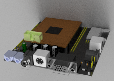
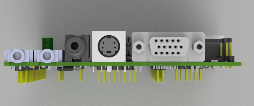
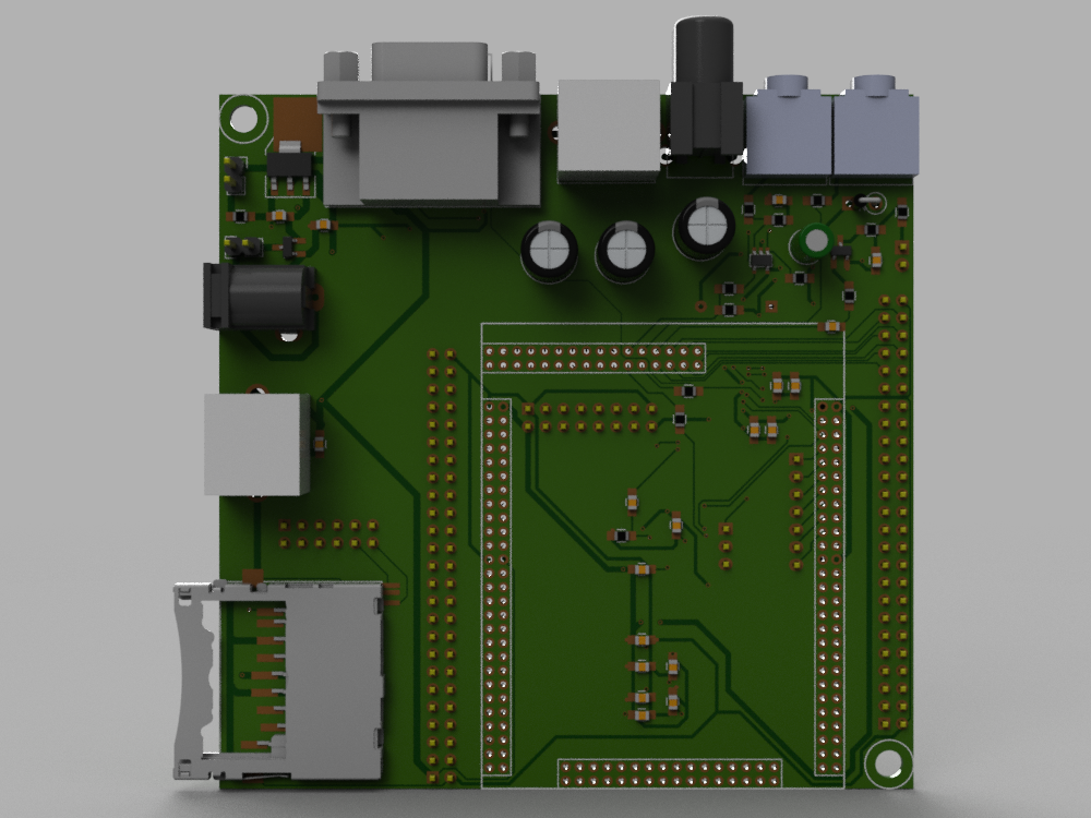
This is what a 3D model of Retrobyte looks like:
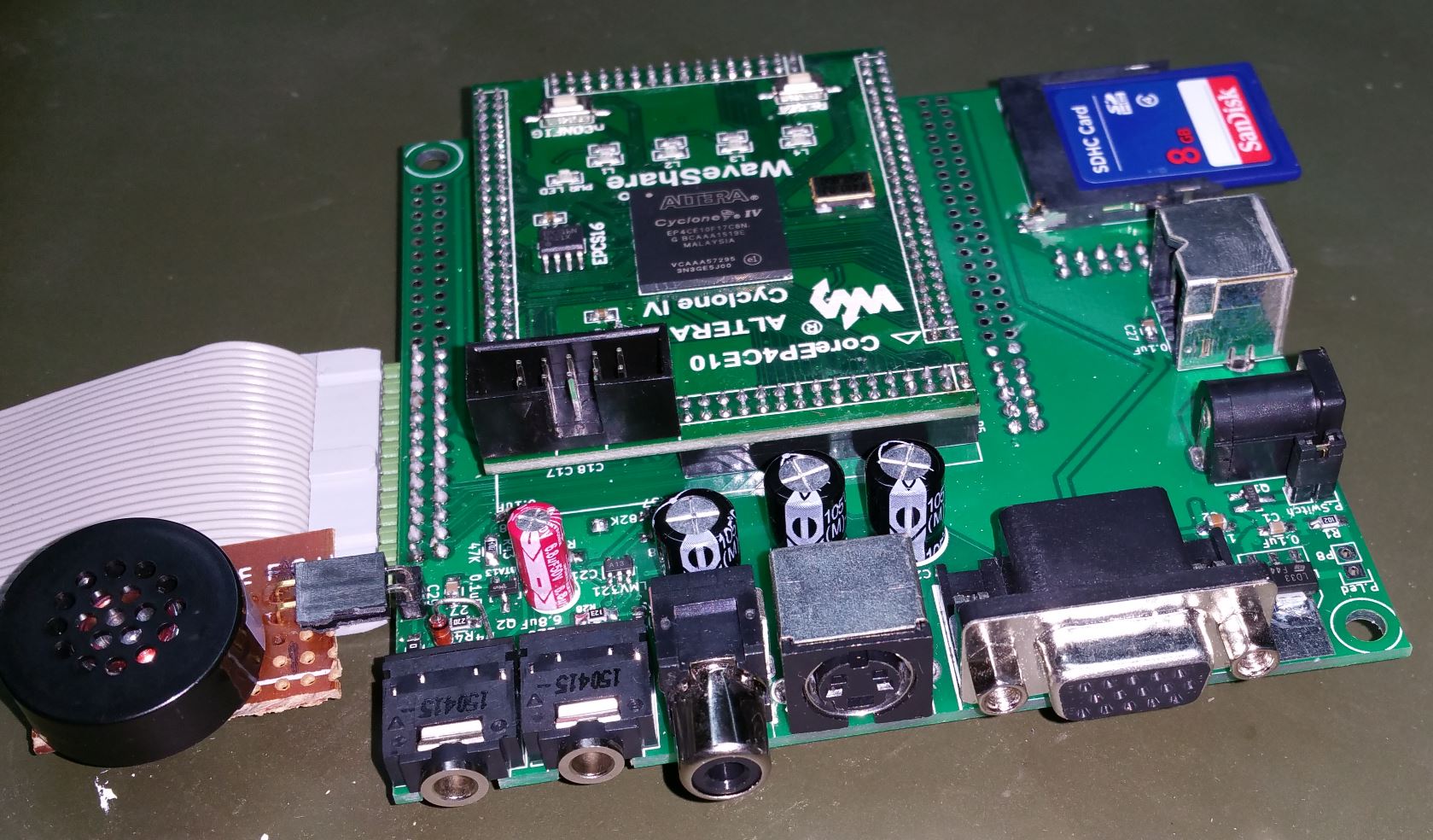
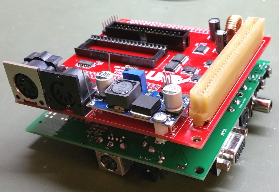
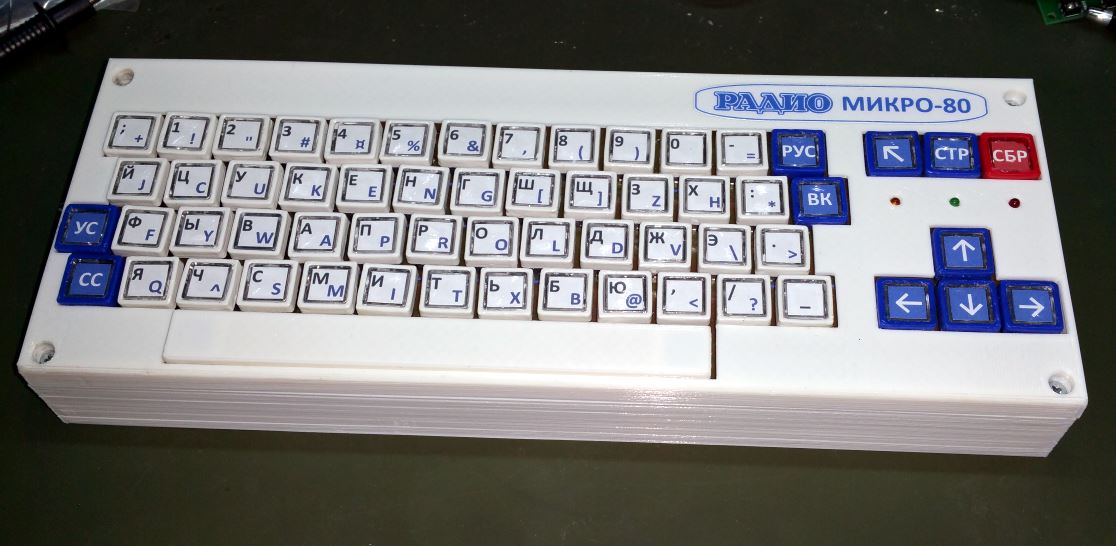
I ordered the boards and built one prototype on which I am currently making a computer “Микро-80” (I will write about this later) to debug and verify the plausibility of the idea. In this process, some inaccuracies were found, which I will remove in Rev.B. All of them are insignificant, so I can still use the boards from Rev.A for building the retro-computers. This is what the finished device looks like:
I will put the schematics and the PCB design up later; once I finish the “Micro 80” computer, I will combine all the changes and fixes and make an improved Rev.B of that board. Watch out for updates!
2 thoughts on “Retrobyte – a universal modular platform for building replicas of retro-computers”
Great!
I’m watching out for updates!