MK-61 programmable calculator keyboard restoration
It’s been a few years since my last post here. Due to changed life circumstances and priorities, I did not have time for this hobby. This site was also abandoned, although I continued to pay for it in the hope of returning. And now, the time had come when I again began to have time for a hobby. I restored this site and changed the design to a more modern one. I hope you enjoy it more than the old one.
I will describe a project I completed about a year ago in this article. Unfortunately, I didn’t save all the project details, so this article will be more descriptive and not an instruction to repeat. However, I will put here everything that I have left. Let this article be the start of a new series of exciting projects!
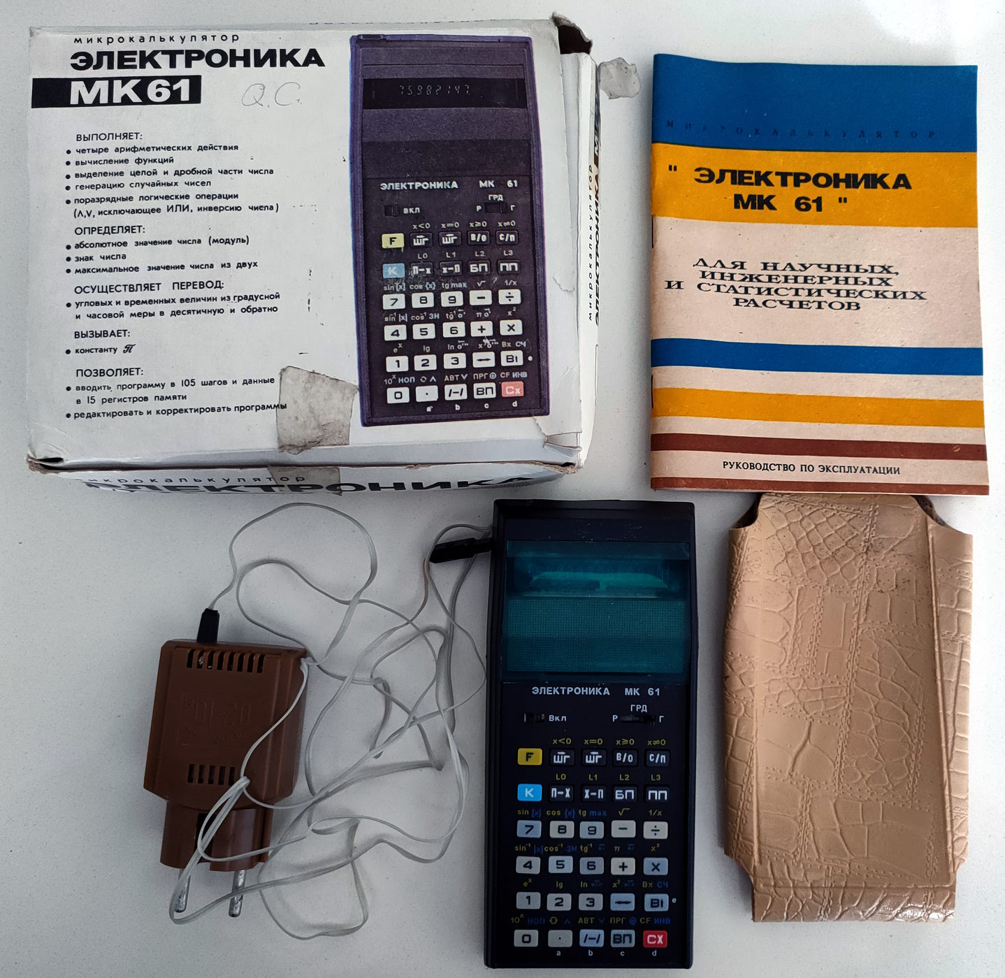
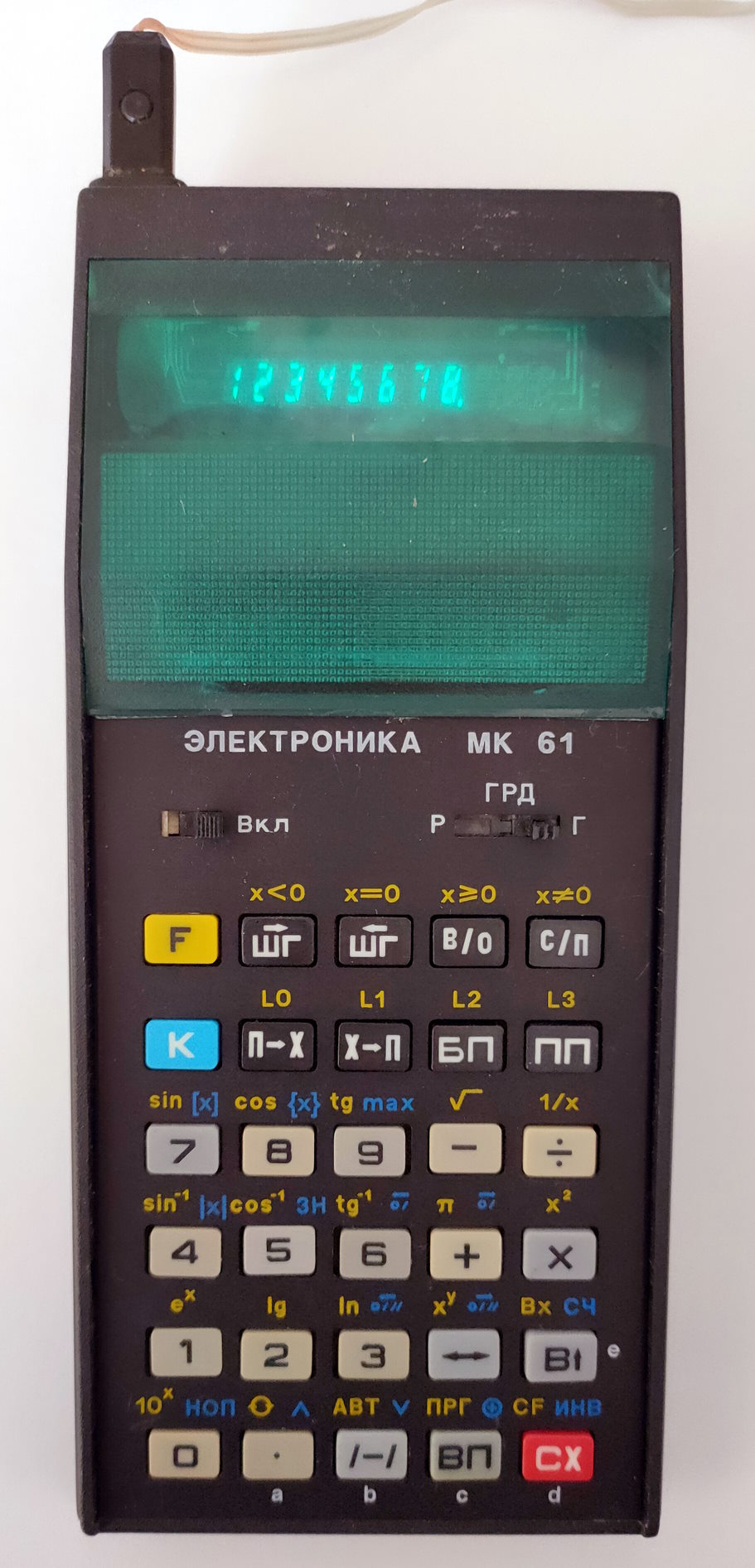
So, I came across an almost new MK-61 calculator on eBay for a reasonable price, and I could not resist buying it. I had one when I was in school, and I have a lot of memories associated with it. I took my first steps in programming on it.
Here are its specifications (taken from Wikipedia):
Year of issue: 1984
Number of digits of the mantissa, order: 8/2
Number of operating registers: 4
Number of addressable memory registers: 15
Number of operations performed: 62
Number of program steps: 105
Non-volatile memory: No
External modules: No
Nutrition: net, 3 AA elements
Price: 70 rubles (1985), 85 rubles later
It uses Reverse Polish Notation (RPN) for the calculations (RPN on Wikipedia), which is very puzzling to those new to it. For example, to add the numbers 3 and 5, you had to press the buttons [3] [enter] [5] [+]. Such a notation is unusual but convenient since brackets are unnecessary for complex calculations.
The condition of the calculator I received was excellent. It was in a factory box (albeit a little worn) with included instructions, a power supply and a case. Its year of issue is 1995. A lovely species for my collection!
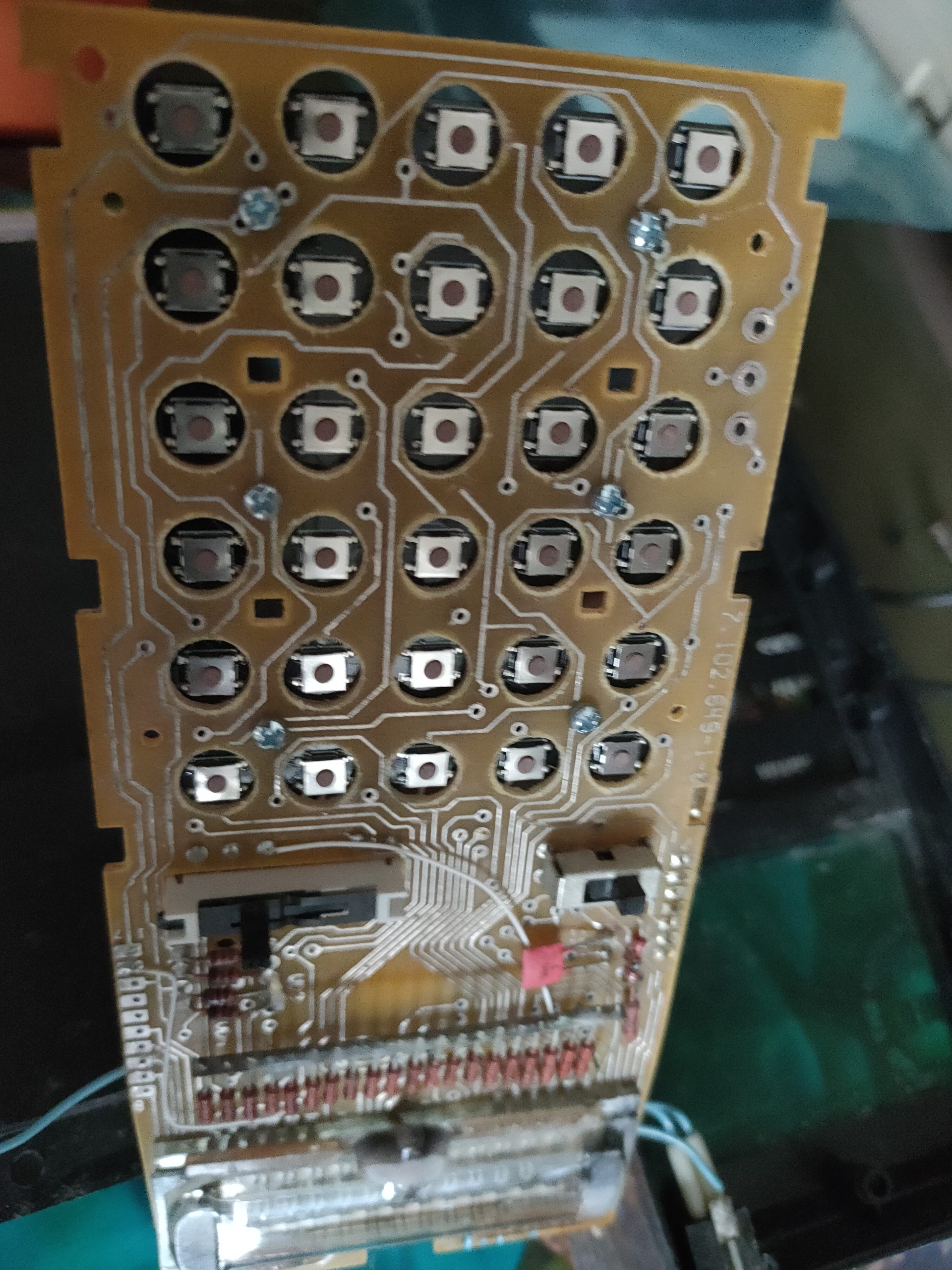
Unfortunately, time did not pass for him in vain, the tracks on the keyboard films began to peel off, and the thin foam padding under the buttons turned into a sticky mass. As a result, the keys did not spring back and did not print what was expected.
Replacing the films seemed difficult since I could not find how to make them. In addition, it would not be easy to restore the lost track pattern and find a way to rivet them to the board to replace the old ones. Therefore, I decided to remake the keyboard with tactile buttons. Looking ahead, I will say that I did it! I now have the first (and so far the only) MK-61 in the world with a mechanical keyboard 🙂 .
The idea was to pick up low-profile SMD tactile buttons, make a PCB for them, drill holes in the calculator board with a diameter matching the external size of these buttons and attach this board to the bottom of the calculator board so that the buttons are inside the drilled holes. This way, they are flush with the board, and the keys will work the same.
To drill the holes in the proper places, I also created a stencil PCB, which I used as a drilling template. It was very cheap to do that due to its small size, but it helped tremendously. Here how both PCBs look like:
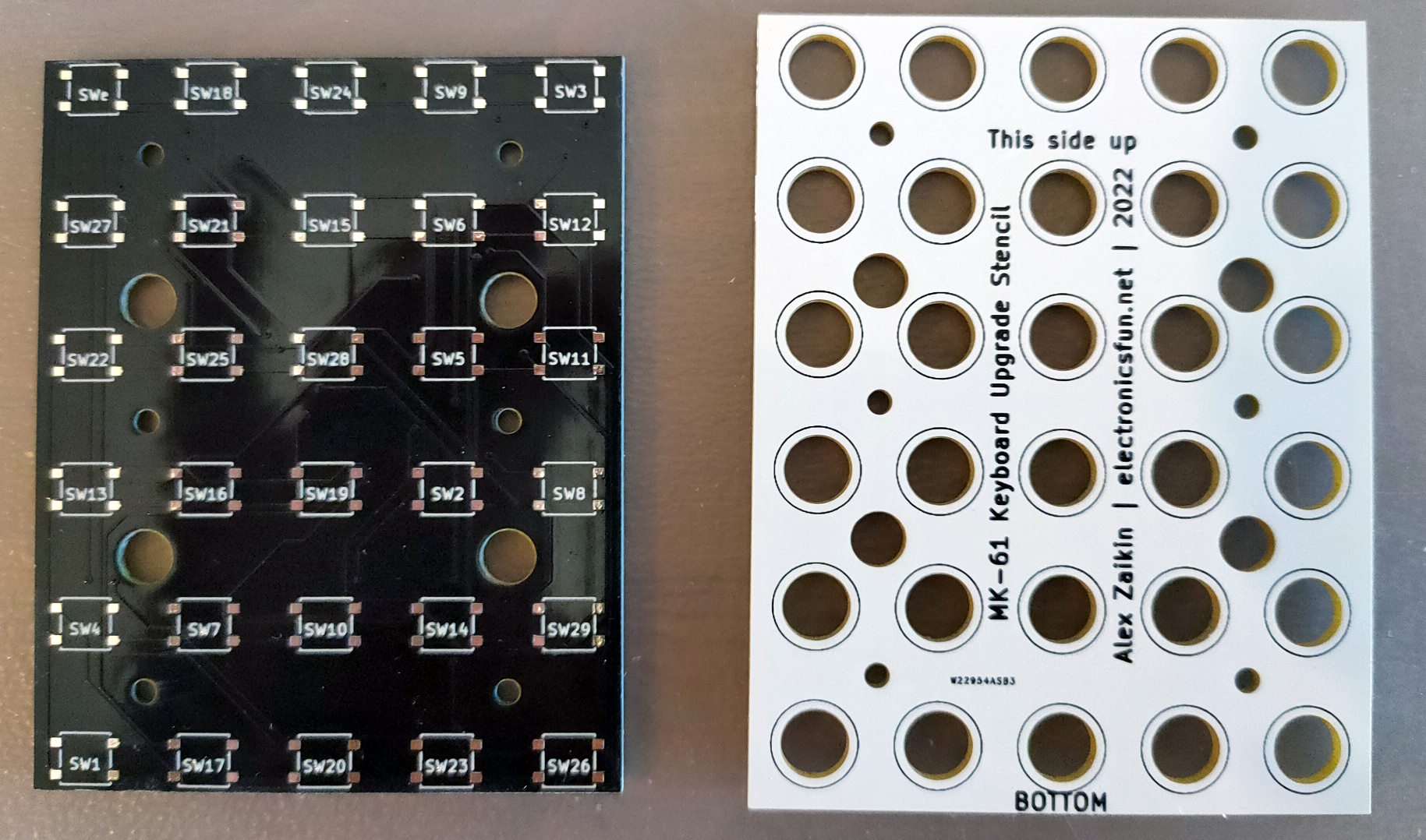
First, I placed the template on the calculator board, aligned it, and drilled a couple of M2 screw holes. Then I fixed the template to the board with screws through these two holes and drilled the rest. The button holes in the template are smaller than necessary to guide the drill better. I used an 8mm drill.
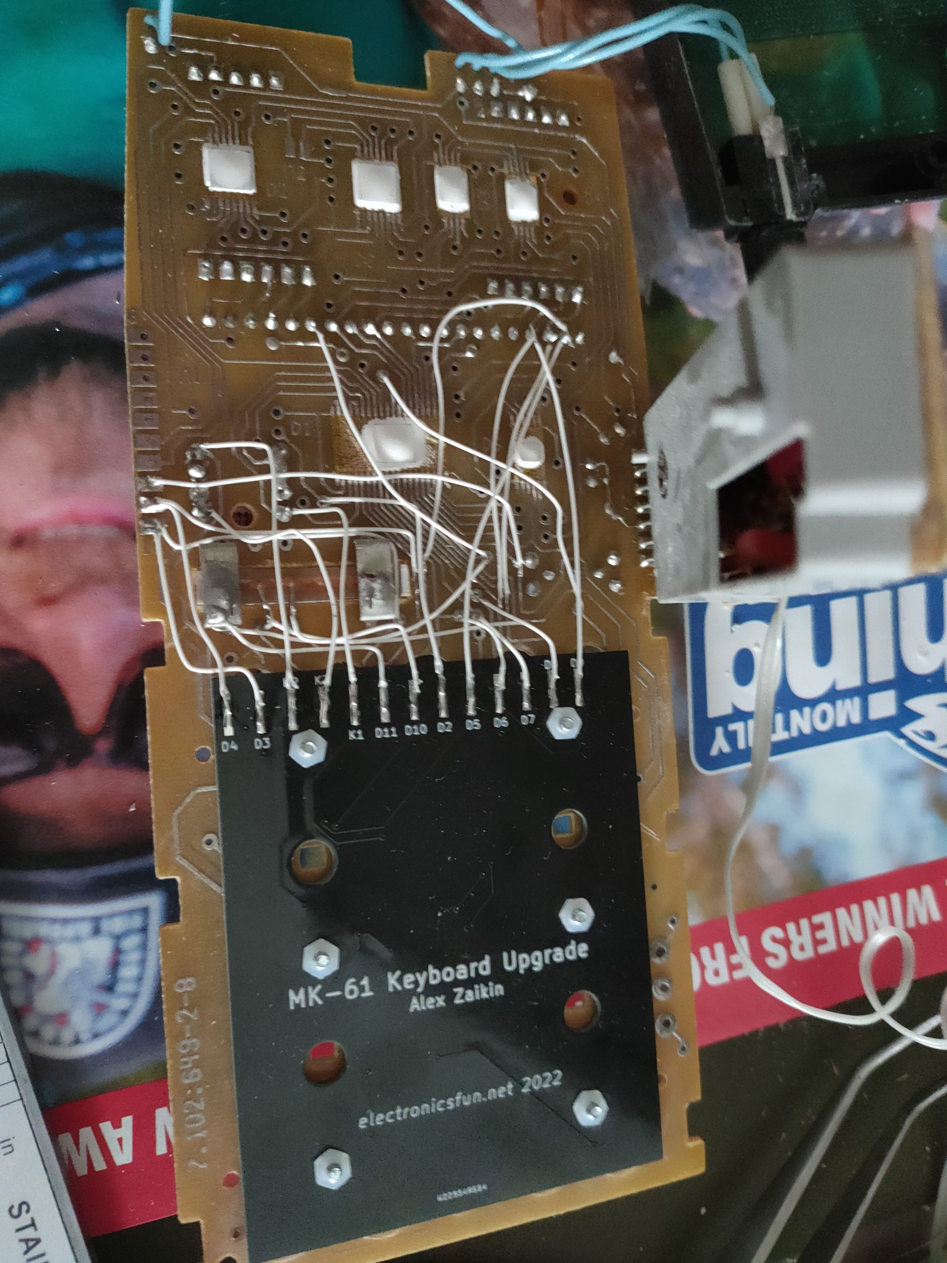
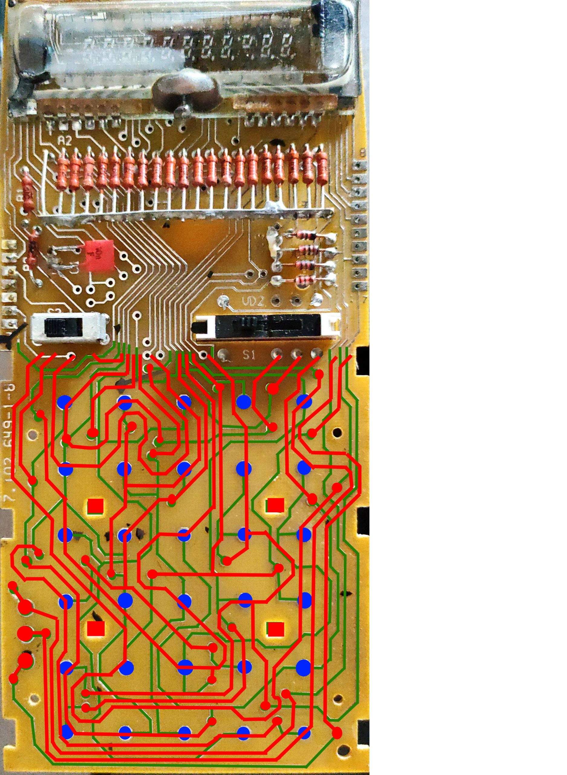
Since the keyboard of the MK-61 is located on the main board and the tracks are to be destroyed during drilling, I had to connect the inputs and outputs of such tracks to the keyboard area with pieces of thin wire to maintain the connection after reaming. Unfortunately, I did this analysis on a sheet of paper with an enlarged scan of the board, and this sheet is lost. So those who want to repeat this project will have to do it themselves. You can find this scan at the bottom of this page and trace the tracks yourself. You can also try using my photos of the modified board for this. The pin designations for soldering wires on the board correspond to the designations on the official calculator circuit diagram, which is easily searched online.
I also had to replace a thin foam pad so the keys do not hang out in the sockets and the springiness is returned when pressed. I ordered a sheet of such material on Digikey, printed a layout with holes on the paper, made an envelope out of it, put this material in it, made holes with a hole puncher for leather and trimmed along the contour. The paper envelope, in addition to the stencil, helped the puncher to cut holes in the foam rubber instead of tearing and wrinkling the material.
The board was made and attached to the calculator board with screws. Track connections lost after drilling are restored with a thin wire. The board with buttons was connected to the corresponding tracks on the calculator board with the same wire. After assembly, everything worked the first time! The calculator keys have acquired a distinct tactile sensation when pressed; the button travel has increased, and, as a result, using such a keyboard has become a much more pleasant experience than the original one. Even though the project was somewhat time-consuming, I would happily recommend it as an upgrade, even with an actual working keyboard.
There is all that I have for this project:
- PCB Gerber files – Download
- Drilling stencil Gerber files – Download
- Two-side calculator PCB scan – Open
- Tactile buttons that were used – Digikey TL3313AF100QG
- Polyurethane foam to replace the old one – Digikey CF40EG 1.5MM
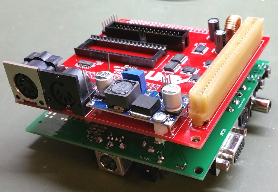
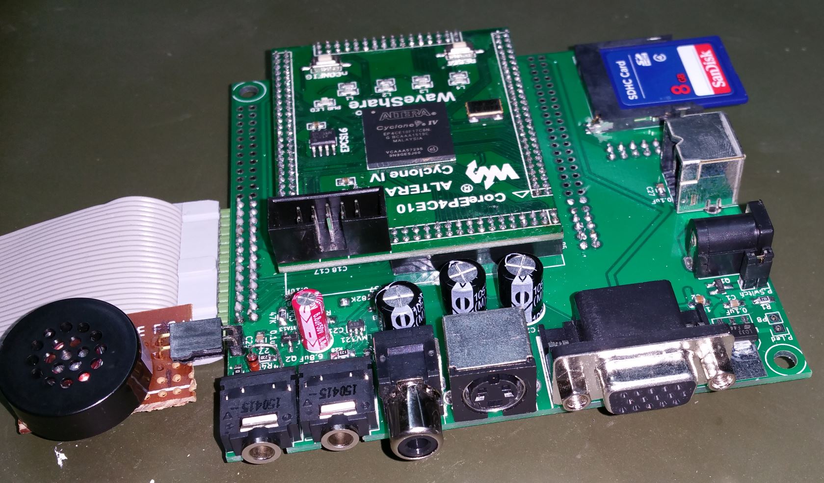
Now I’m preparing for a new retro computer project. Parts and boards are on order, and I will get to work as soon as everything is delivered. This is not the “AGAT” yet, but something more straightforward, which will help me to warm up to get back to the “AGAT” project soon.
See you!