Agat-7. What has been already done.
In this post, I will show what has been done in the project.
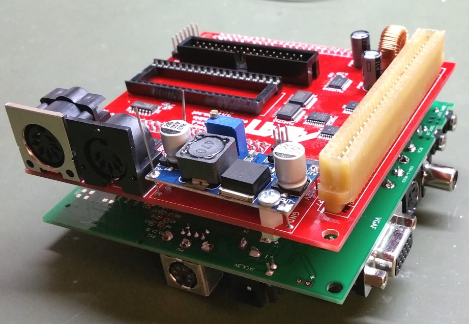
First, an extension board for DE1, which contains a socket for 6502 CPU, was made. I used a toner transfer method to make a PCB. The board connects straight to the GPIO0 header on the DE1 board.
CPU doesn’t require all header pins, so the rest have connectors on the extension board for future use.
AGAT-7 video controller was made in FPGA with VHDL. Now it can display all video modes of the computer. It uses a 1024 x 728 x 65Hz VGA output for this purpose. Early AGAT-7 versions didn’t use luminance bit to display only eight colours. For compatibility with all versions, it is possible to turn on/off this bit (by the switch on the DE1 board), so the controller can display 8 or 16 colours.
I’ve successfully tested all AGAT-7 modes.
All ROMs are located in FPGA as well. It includes two char layouts, a system monitor and a floppy-drive controller program.
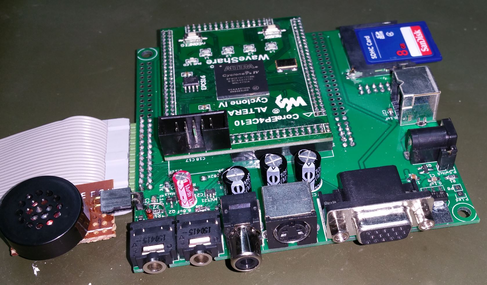
All of the 96Kbytes of RAM are allocated on the SRAM chip on the DE1 board.
The I2S encoder on the DE1 board is used for typing in/out, but I will use an original schematic in the final version.
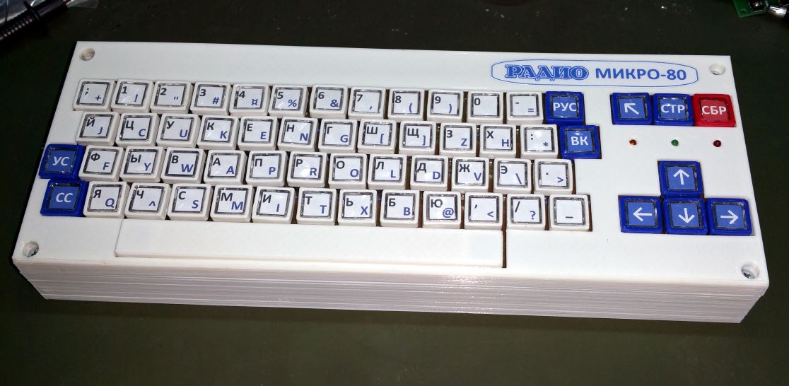
PS/2 keyboard is connected to DE1 and works as an AGAT-7 keyboard. It is impossible to connect the original keyboard yet.
Audio output was made on a breadboard using a modified original schematic.
140K floppy drive was made on a breadboard as well. Now it can read “nib” disk images from a FAT (16 or 32) formatted SD card. An image can be chosen on a 20х4 LCD. Directories are supported. There is no support for long file names to save a microcontroller memory. Also, working with long file names on a small LCD is inconvenient. Another limitation is not more than 80 files in a directory. Despite that, I believe it is enough (a collection of images can be split between directories); I will increase this amount in the next version on the STM32L microcontroller (it has twice more RAM). Write mode to an image hasn’t been done yet:

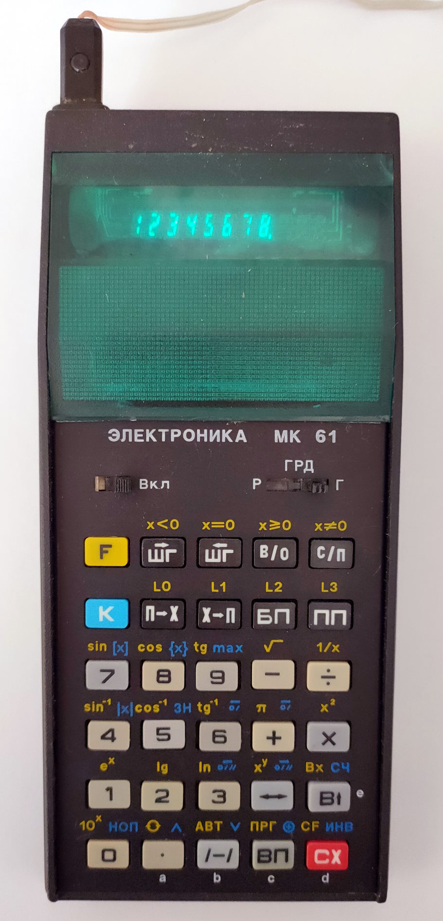
RAM test has been launched from my “floppy drive”:


And here are screenshots of OS “RAPIRA” and “SCHOL’NICA”, which were successfully loaded from my “floppy drive” as well:


Games are also can be launched.
My next steps are:
- Make 840К “floppy-drive” as well (STM32L microcontroller will be used).
- Move the existing 140K “floppy drive” from ATMega64 to STM32L and add a write mode.
- Build tape in/out on a breadboard and test it.
- Make a complete schematic of the project in KiCAD.
- Make Rev.0 of a PCB with all computer elements except serial-parallel interface and extension slot but with accessible pins of FPGA chip and CPU for debugging and developing the rest of the computer.
- Create Rev.A of PCB with all planned devices and slots on it. It can also be used for a DIY kit if there is some interest in it.
That’s it. I hope you like it. Please leave your comments and subscribe to RSS updates. See you!