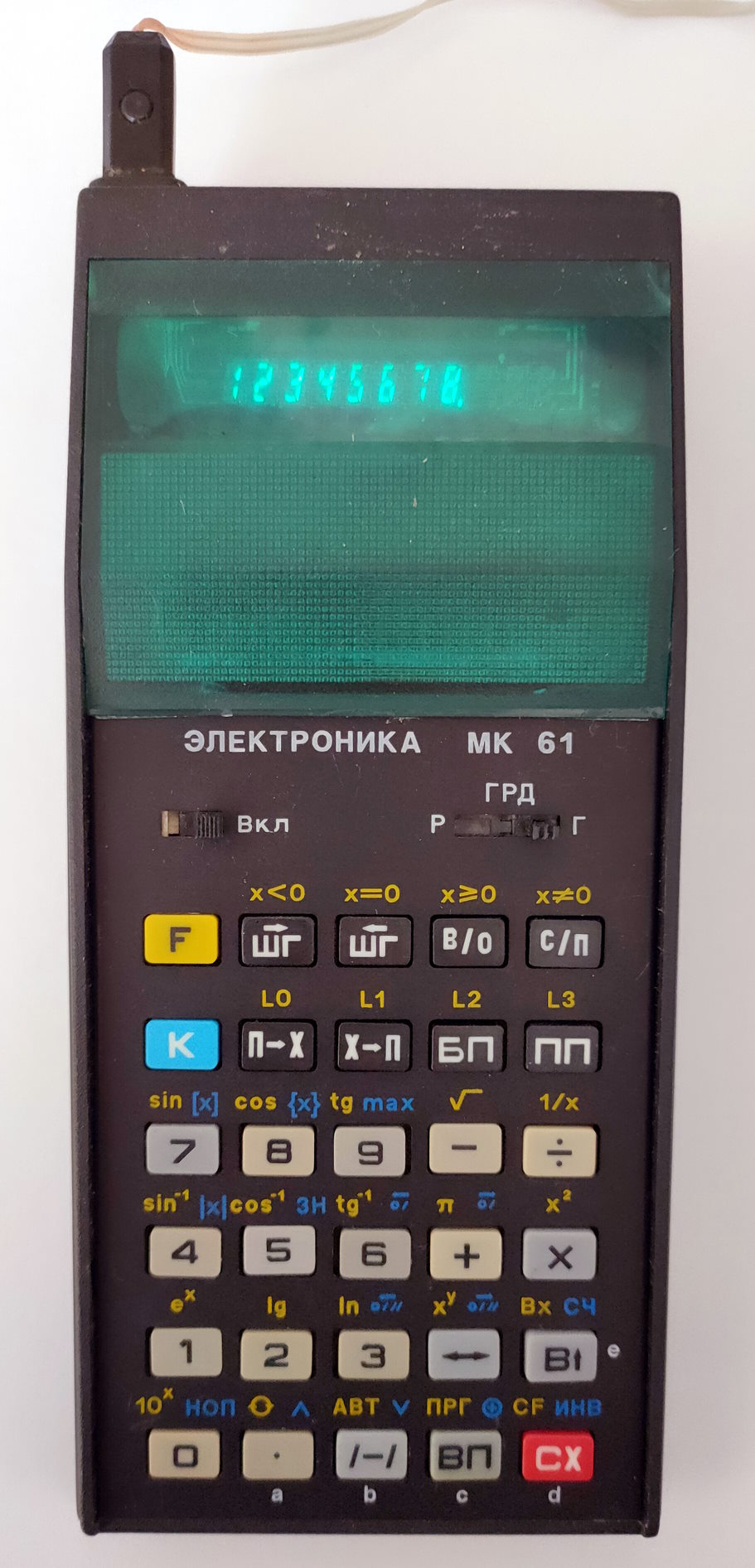
UT-88. Description. Minimal configuration launch
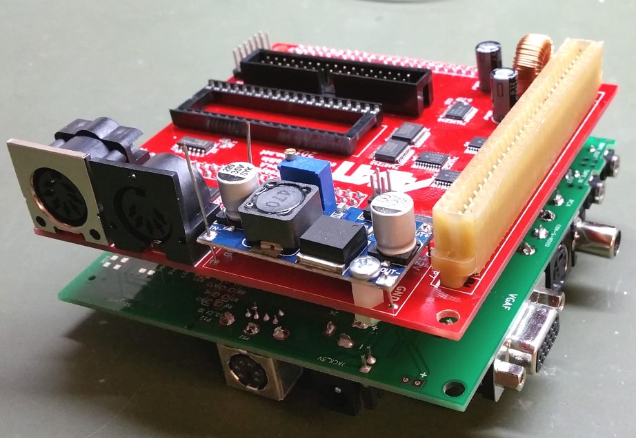
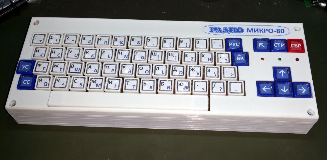
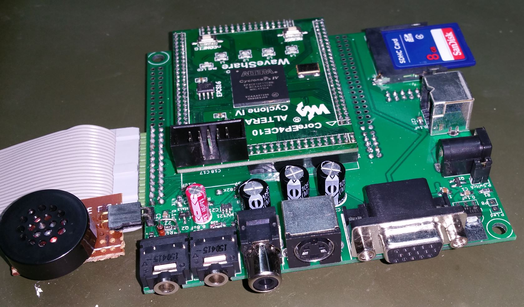
To build the “UT-88” replica, I created an extension board for DE1. I’ve added six 7-segment indicators and a 16-key keypad, almost like the original “UT-88” in minimal configuration. The board should be connected to the GPIO_1 extension header of DE1 to avoid changes in the project. Just in case, I’ve added tape in/out, a buzzer and video out on the board. I haven’t tested any of those except for tape out, so I’m unsure if it works. If you are going to make the board yourself, you can remove all components except the keypad and indicators – nothing else is used in the final version of the project. Such a board can be pretty helpful for other projects as well. Here is its schematic and board layout in DipTrace format: Schematic and layout.
 For those who don’t want to build any other boards but still want to try this computer, I did some modifications:
- 7-segment indicators can be shown on top of the VGA display (use switch SW[0] on the DE1 board to turn this function on/off)
- The connected PS/2 keyboard can be switched to keypad mode (use switch SW[1] on the DE1 board to turn this function on/off)
The replica uses a VGA monitor instead of the TV set. It works in 800х600 60Hz mode. The screen resolution of the “UT-88” computer is 384×224 pixels. For a better fit, I double each dot horizontally and vertically, making each “UT-88” dot occupy four VGA pixels. Picture size becomes 768×448 pixels. It is still insufficient to cover the whole screen, so black borders are around.
I used the top border to show six 7-segment indicators for those who don’t have the extension board.

I use LINE IN and LINE OUT connectors on the DE1 board as tape in and out. Instead of a tape recorder, I use my laptop, connecting it to the corresponding connectors and playing/recording “wav” files. Even MP3 files without high compression do the trick. Instead of a laptop headphone, a CD or MP3 player output can be used. You need to tune the volume correctly to avoid reading errors.
Here are some programs in “wav” format that you can load to the replica: Programs for minimal configuration
The project files can be downloaded here: SOF file (for temporary flash), POF file (to use the device’s flash memory if you don’t want to download it each time you turn DE1 off) and source files.
I use the JTAG interface built into the DE1 board to make life even easier for direct reading/writing to SRAM. Because SRAM on the DE1 board is 16-bit, I use the lowest 8 bits as “UT-88” RAM and the highest 8 bits as a “RAM disk” in the project. So, this interface allows you to read and write the whole memory dump by the “DE1 CONTROL PANEL” utility, which comes with the DE1 board. You can download an example of such dump, which contains OS CP/M and some programs here: Memory dump with CP/M.
HOW TO RUN OUR “UT-88” IN MINIMAL CONFIGURATION
“UT-88” in minimal configuration has the following addressing:
0000 – 0FFF – ROM with “MONITOR-0” and math library. RAM can replace this ROM by switching SW[2] on the DE1 board to the “0” position.
2000 – 23FF – ROM with various programs for computers with minimal configuration. Those programs can’t be run straight from the ROM but can be copied to RAM from address C000 and run from there. This ROM also can be switched off and replaced with RAM by turning on SW[4] on DE1 boards to the “0” position. I’ll describe the list of programs and instructions in my next post about “MONITOR-0”.
С000 – С3FF – RAM for minimal configuration (1 Kbyte).
In our replica, we have access to all RAM in a range from 1000 to FFFF (if “MONITOR-F” ROM is switched off by SW[3]). So, if we switch off ROM with various programs for MONITOR-0 as well (SW[4] to position “0”), we will have access to 60 Kbytes of RAM. Not bad!
7-segment indicators of the computer display the content of memory cells with addresses 9000, 9001 and 9002. As I mentioned before, you can display those indicators on VGA display using switch SW[0] as well as using a PS/2 keyboard instead of the keypad (switch SW[1]). So you don’t need to solder the extension board to try the computer.
When the keypad on the extension board is used, the button “ШН” of the computer is replaced by the KEY[3] button on the DE1 board, and “RESET” is the KEY[0] button. When the PS/2 keyboard is used, all numeric and A, B, C, D, E and F buttons work as a keypad. TAB – is used as the “ШН” button and ESC – as “RESET”.
So, to run our “UT-88” in a minimal configuration, we have to use the following positions of DE1 switches:
SW[0] – “0” if you use 7-segment indicators on the extension board or ‘1’ to use the VGA display.
SW[1] – “0” if you use a keypad on the extension board or ‘1’ to use a PS/2 keyboard instead.
SW[2] – “1” SW[3] – “0” if you are going to use RAM in the range F400-FFFF.
SW[4] – “1” if you want to use additional ROM with programs. You can switch this ROM anytime after you copy a program from there to RAM for use. You can immediately put this switch in the “0” position if you don’t need any programs from the ROM.
SW[6] – “1” to switch on 1Hz timer interrupt. You can keep it “0” if you will not use it.
SW[8] – “0”. If you put this switch in position “1”, the CPU will go to “HOLD” mode. This mode is used for debugging and to read/write memory dumps with the “DE1 CONTROL PANEL” program.
SW[5], SW[7], SW[9] – the position of these switches doesn’t matter in minimal configuration.
In the next post, we will learn how to use the computer in a minimal configuration.