AGAT-7. Rev.0 summary and start of Rev.A design.
I’m finalising my Rev.0 of the modern retro-computer “AGAT-7” replica. The next step will be Rev.A design with fixed mistakes, improvements, and new ideas. In this post, I’m going to summarise the Rev.0 experience and share with you some ideas for Rev.A.
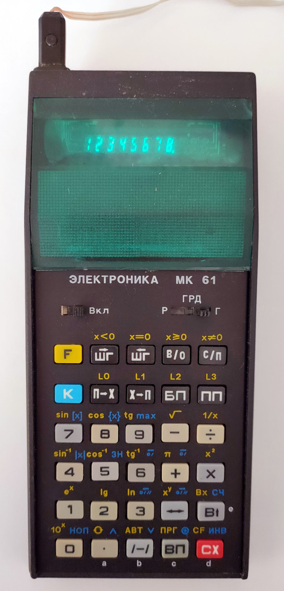
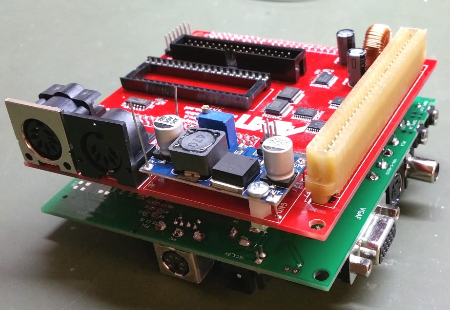
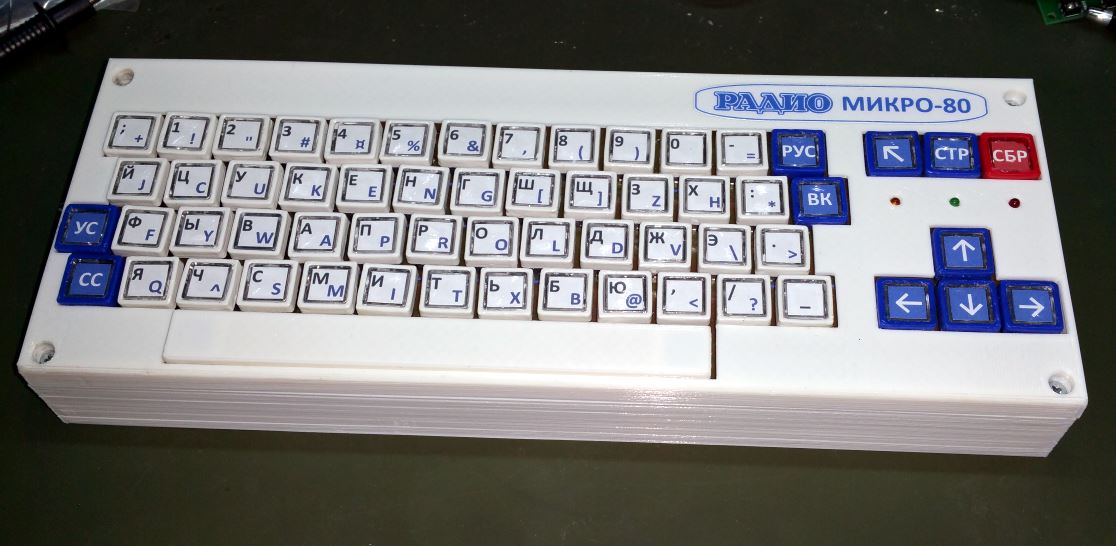
The Rev.0 computer starts and works properly. Here is its photo:

I have been focused more on the hardware part of the project because the software part can be polished later. Rev.0 has quite a lot of mistakes that I had to fix. It wasn’t an easy task with such a tight design. Let’s discuss each part of the computer, see what mistakes were made and what improvements can be made in Rev.A.
- Power supply
The power supply works well. Heat sinks do their job. The hottest chip is the MCP34063, which converts 15V from the input to 6.7V for further conversion to 5V, 3.3V and 1.2V by linear regulators. Its temperature is less than 65C. The other chips’ temperatures are even less than 55C. The computer without extension boards and the original keyboard consumes 250mA.
When I connected the original keyboard, the current increased to 400mA. The temperature of the MCP34063 chip became 70C, and the rest chips had a temperature of less than 65C, which is still fine.
3.3V and 1.2V linear regulators had an incorrect layout, so I had to fix them with wires. Also, I will add a bigger pad for the 3.3V regulator as a heatsink in Rev. A. Aluminium caps need to be moved away from heatsinks as well.
In Rev.A, I want to remove separate switches for each “floppy drive” and the computer. This solution is not good enough because it creates a lot of interference when random switches go on and off. I will leave one main switch, which turns on floppy drives, and the computer can be started later with a “soft”-button after all setup in floppy drives is done.
- Memory
I haven’t done a complex byte-by-byte memory test because I’m not able to connect “floppy drives” on this board (see its section for details). Still, the computer starts, the video works, and random write/read operations to different memory pages work great. I assume that there are no problems in this module.
In Rev.A, I will replace SRAM with SDRAM. I’m currently experimenting with it on the Altera DE1. For the same price as 128Kb SRAM, it will allow 16Mb memory on board that can be used as additional RAM in future updates and store disk images for both floppy drives. In this case, we won’t need the second microcontroller.
- PS/2 keyboard.
The layout of the socket was incorrect, so I had to cut some traces and use some wires. Apart from that, there are no issues with this module. The keyboard works as expected.
- Joysticks.
I don’t have original joysticks to connect and check, and I can’t load a test program because of the floppy-drive issues. Still, when a random resistor is connected to the socket, the module behaves exactly like expected, giving proper output signals depending on the resistor value. The module will remain intact in Rev.A.
I may move it to the extension board if I don’t have enough space on the main board.
- Original keyboard.
The keyboard works as expected, and the module doesn’t require to be changed. But I also consider moving it to the extension board if I run out of space.
- Tape input/output.
The output works great.
In the output schematic, I had to add a 100K resistor between the comparator’s output and ground to make it work. But tests showed that reading is not stable enough with this schematic. I did another module on a breadboard with LM324 opamp (similar to the one used in “Apple IIe”). Its testing shows that with the 3.3V power supply, the output signal is only 2.1V. With a 5V power supply, the output is 3.9V. 3.9V is close to the FPGA maximum of 4.1V, so connecting it through a level shifter is better. I have some spare outputs on the existing shifters.
Temporarily in Rev.0 I will use 2.1V signal, because the FPGA has a 1.8V threshold. Tests showed the excellent quality of the signal. There was only one mistake from 10 test readings. I believe that it will be improved even more with a 5V power supply. The module reads tape records recorded on Rev.0 and with the “AGAT-7” emulator on PC with the same success. The emulator also reads tapes recorded with Rev.0 without any problems.
In Rev.A, the new module based on LM321 (a single version of the quad opamp LM324) will be used. It will be powered with 5V, and a spare level shifter will be used to reduce the output signal to 3.3V.
- Video outputs.
All three video outputs work well. Here are the photos of the output on the VGA monitor and TV through S-Video:
VGA monitor:

TV by S-Video:

The TV picture has a bit of a greyish background compared to VGA, but apart from that, it looks fantastic. RCA output has some artefacts that are noticeable with a close look but not from a 1m distance.
For some reason PAL subcarrier clock generator is not working on Rev.0, so I had to use the FPGA to generate it. I will also use the FPGA for this purpose in Rev.A because this solution is much neater. Also, I will allow PAL/NTSC mode control by FPGA in Rev.A so that a different configuration can be used.
- Sound.
The module works as expected and will be used in Rev.A without any changes.
- 6502 CPU.
The CPU works fine. In Rev.A, I’ll keep the same schematic except for the RESET signal, which will be pulled down instead of pulled up like in Rev.0. It will prevent the CPU from starting before FPGA is configured.
- Extension socket.
I haven’t checked this module because I didn’t want to solder a rare original socket to this temporary board. I don’t expect any issues because the schematic is too simple. Also, I will use a separate extension board with this socket which will be connected to the main board through the standard socket. It will allow connecting different extension boards to the computer in the future.
- FPGA.
Only 25% of Altera Cyclone II is currently used. I don’t expect it to be filled more than 50% when the computer is completed so that the same chip will be used in Rev. A.
The special chip performs
FPGA configuration in Rev.0, which is quite expensive (about $10). Also, it requires to be reprogrammed with each update by the Altera-Blaster programmer.
In Rev.A, I will configure FPGA by floppy-drives microcontroller. A Flash ROM chip must be added and connected with STM32 with the SPI interface. Such Flash ROM chips are very cheap (less than $0.5). And they can be programmed by the microcontroller from SD Card without any additional programmers. However, I’ll leave a connector for the USB-blaster programmer in Rev.A for debugging.
- Floppy-drives.
STM32s PCB layouts were with incorrect pinouts. I’ve fixed some with wires and another in the software, so the 140K drive could start working. I didn’t bother to do the same with the 840K drive because they are identical, and I could debug it with one drive. SD-card and LCD work fine, but I will change this module significantly in Rev.A, so there is no point in continuing with it.
As mentioned, STM32 will be responsible for FPGA configuration and Flash ROM updates from SD-Card in Rev. A. Also, I’ll connect unused pins of the STM32 with pads because it is not fun to solder wires to QFP device J
In Rev.A, only one microcontroller and one SD card will be used. It will put the images of both drives into the SDRAM memory, where the computer can work with them. It will also record the changed image from SDRAM back to SD-Card (if it wasn’t opened in “Read Only” mode).
STM32 will use a 3.2″ colour LCD with a touchscreen. This solution will avoid dip-switches on the board (TV/VGA, keyboard etc. switches). All the options will be shown on the screen and transformed to FPGA by I2C bus from STM32 when changed. Such a display is inexpensive ($15 – $25) but will add a nice touch to the device and save a lot of space on the front panel.
A cheap 1Mb Flash ROM with FPGA configurations can hold up to 6 configurations. So, we can have several different computers recorded there and choose which one to launch on the LCD when the device is turned on. Apart from the “AGAT-7”, we can put “AGAT-9”, “Apple-IIe”, “Commodore VIC-20”, “Atari”, and any other computer with 6502 CPU into the device. Because the extension slot will be external, we can change the adapter for each computer and connect its original devices to it. Determining what adapter is connected and launching the corresponding computer is possible. Because in Rev.A, the FPGA will be able to switch between PAL and NTSC output video signal and generate corresponding subcarrier frequency, the flexibility of the device becomes fantastic.
The size of the Rev.A board will also be changed to fit it into the “Hammond-1598E” case, which is inexpensive and has convenient front and back panels for the LCD and all sockets.
, As a result, the project is transforming from the replica of the “AGAT-7” computer to a universal device that can replicate the whole bunch of 6502 computers and their modifications. In most cases, only the Flash ROM must be updated from an SD card to add a new computer. Even STM32 firmware may not be needed to upgrade in some cases if the new computer uses similar drives. In further revisions, I will think about updating STM32 firmware from an SD card as well, but maybe I’ll be able to do this on Rev.A if I have enough memory left in the microcontroller for the bootloader.
I’m designing the Rev.A PCB and will post news here. See ya!
4 thoughts on “AGAT-7. Rev.0 summary and start of Rev.A design.”
Is design still in progress, or it is frozen?
I’ve got a small kid and still don’t have enough time for such a big project, so I fulfill my hobby with very small projects now. The board’s hardware is ready and running its basic functions. The computer launches with SDRAM and can output to VGA and TV. The challenge is to make the sd-card floppy drive working. As an alternative I’ve tried the HxC floppy emulator with some success. I’m planning to return to this project as soon as I can have enough spare time for it.
Make kickstarter project.
It might be a good idea. But I still need to complete the prototype first. Also, it relies on original 6502 CPU which stock is quite limited. 65C02 has slightly different op codes, so it is not a good substitute. Existing VHDL versions of this CPU are not ideal as well.