Agat-7. Project concept.
Let’s discuss the concept of the replica of the Agat-7 computer. This version is not final and can be (and most likely will be) adjusted. As usual, all your ideas are welcome!
CPU.
The project will use a Bulgarian 6502 clone CM630 as a CPU. But it can be changed to any other 6502 clones because it has the same pins. I am aware that there are some 6502 compatible “soft processors”. I even trialled some of those in the project instead of the “real” one. But they were not 100% compatible with the original 6502 by undocumented commands and cycle times. It can affect compatibility with some programs.
CPU frequency on Agat-7 is 1,021MHz. The replica will use 1.016MHz frequency because it is easier to achieve. It is only 0.5% less than the original and is insignificant.
Memory.
All ROMs will be allocated in FPGA because of their small size. It will include a “System Monitor”, two charsets and ROMs for floppy drives and a serial-parallel interface. It will decrease the quantity of the chips on the board.
RAM will be done on one SRAM (10ns) chip with 128K х 16 sizes (128K of 16-bit words), 256 Kbytes. All 96Kbytes of RAM and 48Kbytes of “Cell 121” RAM will be allocated. The first 8 bits of the 16-bit word are used for even addresses of RAM and the rest for odd addresses. Such allocation is very convenient to use by a video controller because it can read 2 bytes in one step (please, see the Video section below for details).
96K RAM will be connected as 32K of the main system memory, 32K of extended RAM in slot 4 and 32K of ROM emulation card in slot 2.
Video.
There will be RCA, S-Video and VGA video outputs in the replica. A switch can choose the output. VGA output will use 1024 х 768 х 65Hz modes as the most suitable Agat-7 graphics mode. For instance, each dot of 256х256 mode can be displayed on VGA display as a block of 4 pixels in a row in 3 rows (256х4=1024, 256х3=768). But it requires reading video RAM at a much higher speed than in the original computer, and it can be done only during the CPU half-cycle when it doesn’t use buses. To achieve it, 10ns and 16-bit SRAM memory are used, which allows to read 2 bytes of RAM at one step and do enough of such steps during the CPU half-cycle to fill a buffer with enough data to display until the next CPU half-cycle.
VGA output will be the main. TV outputs will be built with an AD725 chip.
“Cell 121”, which allows launching Apple-][ programs on the computer in its graphic modes, will also be created in FPGA.
Initially, the Agat-7 computer was manufactured with a charset containing only capital letters, but it was replaced with the full charset. For compatibility, both charsets will be used in the replica with the option to switch between them at any time with a toggle switch.
Sound.
A speaker will be used for sound output with a similar schematic as in the original computer with some changes (for instance, a Darlington transistor will be replaced with a MOSFET).
Tape in/out.
Most likely, the schematic from the original computer will also be used because of its simplicity. But some tests are required to ensure it is reliable enough as an alternative I2S encoder/decoder chip can be used.
Keyboard.
The computer will have two keyboard sockets. One for the usual PS/2 keyboard and another for the original keyboard. There will be a switch to choose the source.
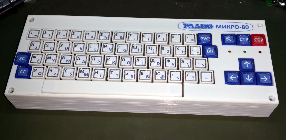
Also, an analog of the original keyboard will be built for those who want a better experience but don’t have an original keyboard. An ATTiny microcontroller will be used for it.
140K floppy drive.
There is no intention to use a real floppy drive in the replica. Instead, the 140K floppy drive in slot 3 will be emulated with an ATMega644 microcontroller. It can be switched off. LCD alphanumeric 20×4 display will be used to choose a disk image from an SD card with the FAT32 file system. It will emulate a floppy disk drive using the image. It will be possible to write and read from the image. Disk image format needs to be 227.5 Kbytes .nib format. A photo can be opened in read-only or read&write modes. Photos have to be recorded to an SD card before use.
The microcontroller requires a 5V power supply to work on 20Mhz, so that it will be this module’s primary voltage. A buffer chip TXB0104 will communicate with the SD card (which requires 3.3V).
The LCD will be connected to the 4-bit bus.
840К Floppy-drive.
There is no intention to use a real floppy drive in the replica. Instead, the 840K floppy drive in slot 5 will be emulated with an STM32L152 microcontroller.
The reason for using the STM32 microcontroller instead of ATMega is its ability to support DMA exchange and has more than 1.5 times higher working frequency. It is essential for 840K floppy-drive emulation because it requires twice higher exchange speed than 140K. The prices for both microcontrollers are almost the same.
Using the same microcontrollers in the project would be better, but I have already created the 140K device, and I don’t see any point in rewriting it for STM32 at this stage. Maybe it will be done in one of the following revisions.
The floppy drive can be switched off. LCD alphanumeric 20×4 display will be used to choose a disk image from an SD card with the FAT32 file system. It will emulate a floppy disk drive using the image. It will be possible to write and read from the image. Disk image format needs to be 2,020 Kbytes .aim format. A picture can be opened in read-only or read&write modes. Images have to be recorded to an SD card before use.
A 3.3V power supply will be used for the module. A buffer chip will be used to communicate with a 5V LCD.
Each floppy drive will be independent of each others and have its own SD card slot and control.p>
Serial-Parallel Interface (SPI).
This extension board will be emulated in slot 6 and can be switched off with a toggle switch. It will have an external socket, but it won’t be an original socket (it is difficult to buy it now). A standard IDE socket will be used instead. Devices can be connected to this socket with adapters.
The SPI will be built on CPLD Altera MAX I.
Extension slot.
It will be possible to connect extension boards to the computer. The original socket for extension boards will be used. Any original board can be connected to it and recognized in slot 6 or turned off by a toggle switch. This slot can be used, for instance, to connect an original floppy-drive controller to copy actual disks to an SD card.
Power supply.
The computer will require an external 15-19V DC power supply. Most laptop power supplies can be used (but an adapter may be required). The computer will have the following power lines: 12V (for SPI), 5V, 3.3V and 1.8V (for FPGA). Linear DC-DC converters will be used. Instead of a standard ATX power supply unit, this solution was used to make the computer fit in a compact enclosure.
Enclosure and PCB.
A 2-layer PCB will be used with extensive use of SMD components. LCDs and controls will be allocated on top of the main board. Most of the computers will be in FPGA chip Altera Cyclone II EP2C5T208. To save FPGA pins multiplexers for keyboards, floppy drives, video outputs etc. It will be used. For signals that don’t require high-speed responses (switches, indicators etc.), an I2C port extender will be used.
Kits for DIY will be designed if enough interest exists.
In the following posts, I’ll describe what has already been done and give some examples from the project. Please, subscribe and leave your comments. See you!


