Agat-7. Rev.0. Floppy-drives emulators.
At the moment, I’ve completed the schematics, and I’ve started to work on the PCB layout. There will be some changes caused by discovered mistakes or better layouts. So, please, treat it as a draft at this stage. Please, let me know if you notice any errors.
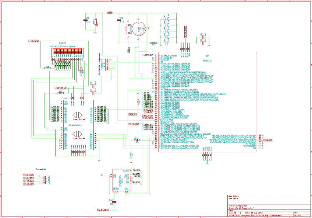
Today we will have a look at schematics of 140К and 840К floppy drives:
As you can see, they are almost identical. I’ve only used different LCD colours for them. I used this schematic as an example in my post about LCDs. In the current version, LEDs were added, card control pins were connected, and pins for communication with FPGA were determined. The communication is performed with the SPI interface. It is enough to use four wires for this, but I’ve added the 5th, which is used for the subsequent byte request. It happens each 32nd CPU cycle for a 140K floppy drive, and it exact match with the speed of the actual drive. On a breadboard trial, I got a lot of errors because of connections and wires length, so I had to send each byte triple times to reduce the errors. It is the reason for the 5th wire. I could remove it in my final design and use each SPI session as a byte request. But, just in case, I’ll leave it in Rev.0 design. Also, the microcontroller connected to the I2C port extender with “ready” and “write enable” signals.
When turned on a floppy drive, it scans an SD card and shows its content on the LCD. It recognises FAT16 and FAT32 formats. It doesn’t have long filenames support because the display size is limited anyway. There is a limit of 100 files and subfolders in a folder. Files that are not images are ignored and not counted in the limit. For 140K, floppy-drive .nib files are used. Its size should be 227.5Kb. 840K floppy drive uses .aim file format. It should be kept in mind when the collection of disk images is created on the SD card. Floppy drives cannot create new images but will be able to write to the existing image, so “empty” images have to be made on the SD card if required. An image can be chosen with the rotary encoder from the file list. If the SD card is not write-protected, selecting a mode – “read-only” or “read&write” before an image is opened is possible. After that, the microcontroller starts a floppy drive emulation. It uses the SPI interface to communicate with FPGA. “Floppy drives” have their power switches independent of the main switch. It allows to start emulation before the computer is turned on, so it will see a disk in a “drive” and perform the autoboot from it.
The next part of the schematic will be discussed in the following post. See you!


